


– 206 –
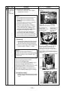
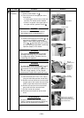
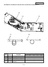
Screws
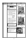
Front cabinet
Inverter cover
Cord clamp
Screws
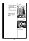
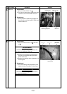
(Discharging
period
10 seconds
or more)
Plug of
soldering iron
Discharging
position
Inverter
assembly
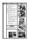
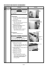
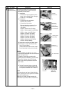
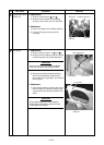
Remove the connectors
with locking function by
pushing the part indicated
by the arrow mark.
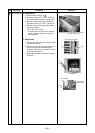
No.
3
Part name
Inverter
assembly
Procedure
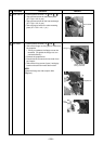
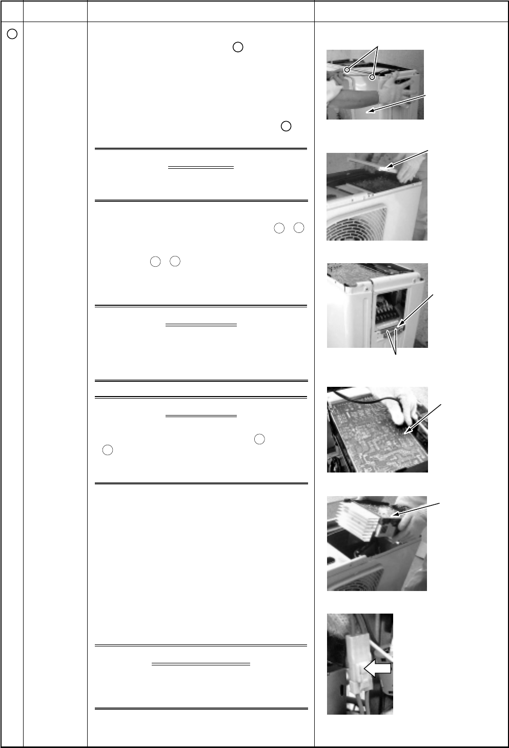
1. Detachment
1) Perform work of item 1 of
1
.
2) Take off screws of the upper part of the
front cabinet.
• If removing the inverter cover under this
condition, P.C. board can be checked.
• If there is no space in the upper part of
the upper cabinet, perform work of
2
.
XCAUTIONX
Be careful to check the inverter because
high-voltage circuit is incorporated in it.
3) Perform discharging by connecting
+
,
–
polarities by discharging resistance
(approx. 100Ω, 40W) or plug of soldering
iron to
+
,
–
terminals of the C14 (printed
as “CAUTION HIGH VOLTAGE”) electrolytic
capacitor (500µF) of P.C. board.
X WARNINGX
The electrolytic capacitor may not normally
discharge according to error contents and
the voltage may remain. Therefore, be sure
to discharge the capacitor.
X WARNINGX
For discharging, never use a screwdriver and
others for short-circuiting between
+
and
–
electrodes. As the electrolytic capacitor is
one with a large capacity, it is very danger-
ous because a large electric spark will occur.
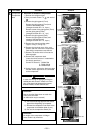
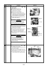
4) Take off screws (ST1T Ø4 × 10L, 2 pcs.)
fixing the main body and the inverter box.
5) Remove various lead wires from the holder
at upper part of the inverter box and wiring
holder at right side of the terminal block.
6) Remove the lead wire from the bundled
part at left side of the terminal block.
7) Pull the inverter box upward.
8) Disconnect connectors of various lead
wires.
XREQUIREMENTX
As each connector has a lock mechanism,
avoid to remove the connector by holding the
lead wire, but by holding the connector.
Remarks