– 146 –
11-2. Outdoor Unit
1. Setting the jumper wires and DIP switches
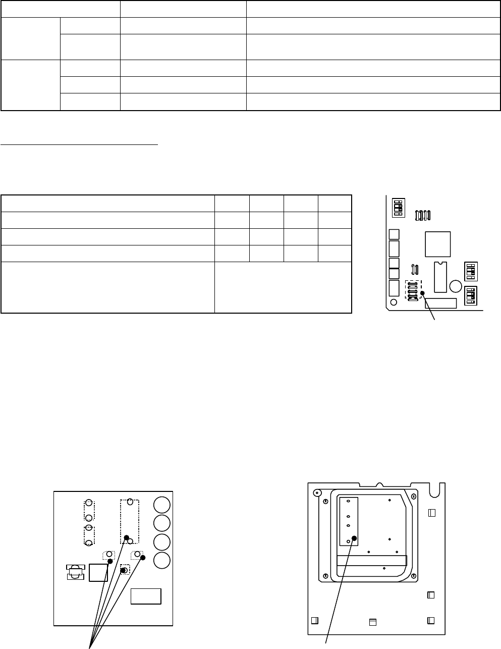
Model switching (J800 to J803)
Since this service P.C. board is available for several models, cut the jumper wires according to the following table.
If they are not cut correctly, an error code “L10” or “L29” appears on the remote controller and the operation of the air
conditioner is disabled.
2. Installing the P.C. board
1) Apply thermal grease to the back (heat sink contacting side) of devices Q200, Q650, DB01, and DB02.
( Q300 and Q400 are not necessary to be applied thermal grease.)
2) Reuse the insulating sheet. When a small amount of thermal grease is applied to the back of the insulating
sheet, it adheres temporarily to the heat sink, which makes it easy to attach the insulating sheet.
3) Insert the P.C. board, align the holes of the insulating sheets, semiconductor devices, and heat sinks, and
then secure them with screws.
4) Connect the lead wires according to the wiring diagram sticked on the backside of the pannel .
J800 to J803
Apply thermal grease to
the back (heat sink contacting side) of
Q200, Q650, DB01, and DB02.
Reuse the insulating sheet.
Applying thermal grease to the back
of the insulating sheet makes it easy
to attach the insulating sheet.
<In case of SP110, SP140>
Model name
Factory setting (default)
RAV-SP1104AT
∗
-E
RAV-SP1404AT
∗
-E
∗ : Characters that indicate the following:
No character ...... Standard models
Z ......................... For salt-affected areas
ZG ...................... For heavily salt-affected areas
J 800 J 801 J 802 J 803
¡¡¡¡
× ¡¡¡
¡ × ¡¡
¡
: Connected,
×
: Cut
Part name
J800 to J803
Jumper wire
J804 to J810
SW802
DIP switch SW803
SW804
Function
Model switching
Settings
Settings
LED indication switching
Special operations for service
Setting
Cut these jumper wires according to the following table.
Set these jumper wires to the settings of the P.C. board before
replacement.
Set SW802 to the setting of the P.C. board before replacement.
Set SW803 to all OFF.
Set SW804 to all OFF.


