


– 195 –
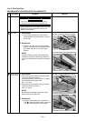
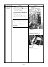
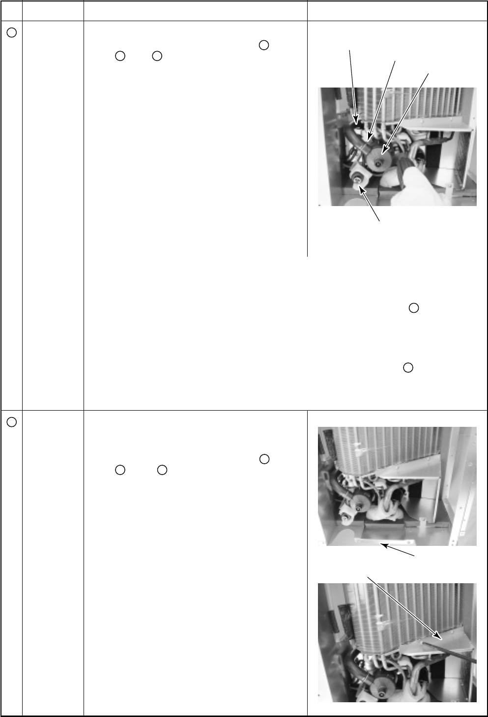
Drain pump
Hose band
Drain hose
Float switch
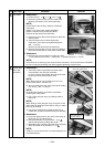
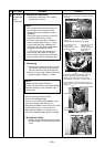
Pipe holder
Heat exchanger support board
(Pipe side)
No.
9
10
Part name
Drain pump,
Float switch,
Drain hose
Evaporator
assembly
Procedure
1. Detachment
1) Perform works in procedures 1. of
2
, 1. of
3
, 1. of
8
.
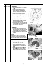
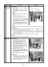
2) Disconnect lead wires which are connected
to the following connectors of P.C. board
assembly.
NOTE)
Unlock locks of the housing to remove the
connectors.
CN34 : float SW (3P: Red)
CN504 : Drain pump lead (2P: White)
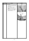
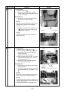
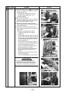
3) Loosen hose band, remove cap of the drain
hose, and take off screws while holding drain
pump. Remove them with care that pipes are
not damaged. (Ø4 × 10, 3 pcs)
4) Take off screws while holding metal on float
switch. Remove them with care so that
pipes are not damaged. (Ø4 × 10, 1 pc)
NOTE)
If the pipes are damaged, refrigerant leak may be caused. Take out them with great care.
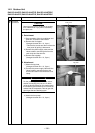
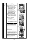
2. Attachment
1) Attach ASSY sheeting metal which was removed in procedure 1. 3) of
9
with care that
pipes are not damaged, and then fix it with screws.
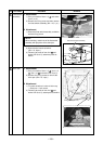
2) Insert the drain hose into the inlet of drain pump, and then fix it with hose band. Arrange
handle of the hose band at contrary side of heat exchanger side and at direction remote
from drain pan assembly.
3) Carry out wiring as before, and then perform work of procedure 2. of
8
.
NOTE)
Finally check whether they correctly operate or not.
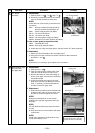
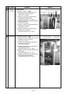
1. Detachment
1) Recover refrigerant, and then remove
refrigerant pipes at indoor unit side.
2) Perform works of procedures 1. of
2
, 1. of
3
, 1. of
8
. Remove sensors.
3) Take off screws of the pipe holder, and
remove the pipe holder. (Ø4 × 10, 2 pcs)
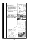
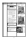
4) Take off screws of the heat exchanger
support board (Pipe side), and remove the
heat exchanger support board
(Pipe side). (Ø4 × 10, 4 pcs)
5) Take off screws of the heat exchanger
support board (Opposite side) which fixes
terminal block of the evaporator assembly.
(Ø4 × 10, 2 pcs)
6) Remove the evaporator assembly.
2. Attachment
1) Fasten the parts as before in order, Evapora-
tor assembly → Pipe holder → Set sensors
→ Drain pan assembly → Under panel.
2) Connect the refrigerant pipe as before, and
then perform vacuuming.
Remarks