


– 198 –
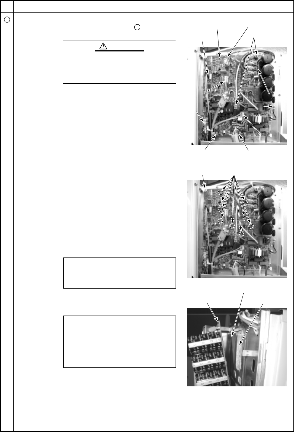
Control P.C. board
Compressor
case thermo.
Upper fan motor
Reactor lead
Compressor lead
Compressor lead
Ear
Ear
th wire
th wire
Lo
Lo
wer
er
fan motor
an motor
Temper
emper
ature
ature
sensor
sensor
Compressor lead
Earth wire
Lower
fan motor
Temperature
sensor
4-w
4-w
ay valv
alv
e coil
e coil
4-way valve coil
PMV coil Indoor power supply
P.C. board
fixing screw
Insulating sheet
Control P.C. board Sealing material
Element fixing screws
(9 positions)
No.
4
Part name
Replacement of
electric parts
Procedure
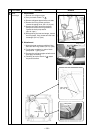
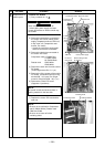
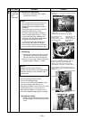
1. Control P.C. board
1) Carry out work of 1 of
1
.
X WARNINGX
Never disassemble the inverter for
1 minute after power supply has been
turned off because an electric shock may
be caused.
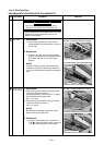
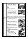
2) Remove the connectors connected to
the control P.C. board. (Indoor power
supply, Temperature sensor, PMV coil,
4-way valve coil, Compressor case
thermo, Fan motor)
• Unlock the lock of the housing part
and then remove the connectors.
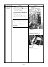
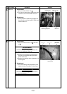
3) Remove the lead wires connected to
the control P.C. board.
Compressor lead U: CN200 Red
V: CN201 White
W: CN202 Black
Reactor cord CN05 White
CN06 White
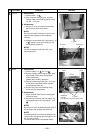
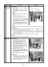
4) Remove the earth wire from the control
P.C. board.
(Trust B tight screw Ø4 × 6, 1 pc.)
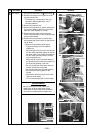
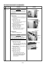
5) Remove the fixing screws of the control
P.C. board. (Screw with collar for fixing
element Ø3 × 16, 9 pcs. Pan S tight
screw for fixing board Ø3 × 20, 1 pc.)
6) Remove the control P.C. board.
(Supporter: 5 positions)
NOTE :
Be careful to take out because there is
sealing material for the heat sink.
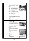
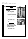
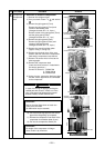
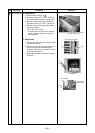
7) Replace the control P.C. board with a
new one.
NOTE :
• Be sure not to confuse for Compressor
lead V (CN201 White), Reactor lead
CN05 and CN06.
• Be sure not to come-off of the
insulating sheet.
Remarks