


To view the current dark offset, press SETUP-MORE-DARK-VIEW. Press EXIT
when finished. No password is required to view the dark offset, only to change it.
9.4 Output voltage range changes
Output voltage ranges are set by DIP Switch settings on the V/F board. To change the
range for the analog outputs:
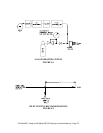
1. Turn off instrument power. Remove the instrument cover. Locate the V/F
board near the top of the drawing using Figure 1.6.
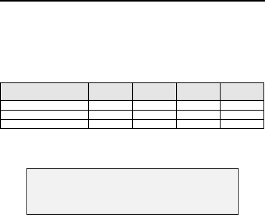
2. Locate switches S1, S2, and S3 along the top edge of the card. Select the
desired range by setting the switches as shown in Table 9.1, below.
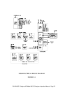
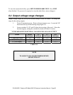
V/F BOARD SWITCH SETTINGS - RANGES FOR ANALOG OUTPUT
Switch 100 mV
Full Scale
1 V
Full Scale
5 V
Full Scale
10 V
Full Scale
S1 (Recorder Output) 1, 6 1, 5 1, 4 1, 3
S2 (DAS Output) 1, 6 1, 5 1, 4 1, 3
S3 (Test Output) 1, 6, 7 1, 5, 7 1, 4, 7 1, 3, 7
TABLE 9.1
NOTE
TO ADJUST ANALOG RECORDER OFFSET,
SEE SECTION 4.7.
P/N 02163G1 Teledyne API Model 300 CO Analyzer Instruction Manual - Page 80