


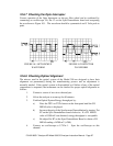

5. Confirm the wave from of the optical signal by attaching an oscilloscope
to the Sync Demodulator board a U2 Pin 7. The oscilloscope trace should
appear like those shown in Figure 10.2. In particular the wave form
should be symmetrical and should have distinct flat regions at the top and
bottom of the pulses.
6. If unable to achieve 4200 mV on CO MEAS, then do the following:
7. Adjust source for maximum signal strength. Typically source has no
effect on wave shape. (Not to exceed 27V peak to peak.)
8. Adjust input mirror as needed to create a wave shape with distinct
flattening of the peaks and symmetrical “Knees” at the peaks. A smaller
waveform with nice symmetry is preferable to a larger one which is
asymmetrical.
9. With zero air in, verify an MR RATIO of 1.18 to 1.22 is desired. If the
analyzer shows a significantly different value, slightly adjust the input
mirror.
10. Adjust R7 for a CO MEAS reading of 4200 ±200 mV.
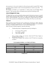
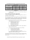
P/N 02163G1 Teledyne API Model 300 CO Analyzer Instruction Manual - Page 98