


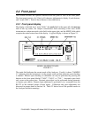

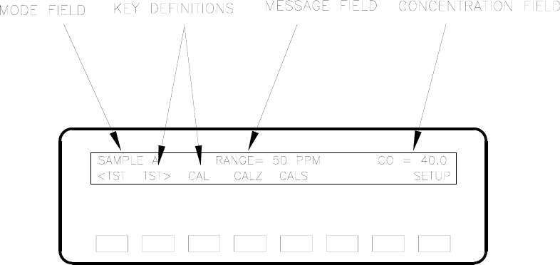
ILLUSTRATION OF NORMAL DISPLAY
FIGURE 2.2
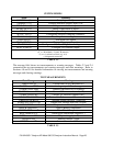
If TEST is pushed, the upper center display cycles through the menu of test parameters,
e.g. Sample flow (see Table 2.3). If CALZ is pushed, the sequence of operations for
setting the Analyzer zero is initiated(see Section 3.1).
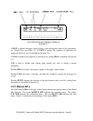
If CALS is pushed, the sequence of operations for setting SPAN is initiated (see Section
3.1).
CAL is used to initiate span setting using sample gas, such as during a formal
calibration.
Pushing MSG will cause a message to appear on the upper center display.
Pushing CLR will erase a message, provided the condition causing the message has
ceased.
Pushing SETUP changes the function of the push buttons and is used for setting basic
parameters as described in Section 4.0.
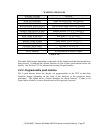
2.2.3 Status LED’s
The three status LED’s to the right of the display indicate the general status of the Model
300 Analyzer. The green SAMPLE LED indicates the sampling status. The yellow
CAL LED indicates the calibration status. The red FAULT LED indicates the fault
status. Table 2.5 summarizes the meanings of the status LED’s.
P/N 02163G1 Teledyne API Model 300 CO Analyzer Instruction Manual - Page 28