


1.8 Options
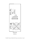
1.8.1 Rack mount with slides
This option, including slides and rack mounting ears, permits the Analyzer to be mounted
in a standard 19" wide x 30" deep RETMA rack.
NOTE
A 1¾" MINIMUM SEPARATION BETWEEN EACH
INSTRUMENT MUST BE MAINTAINED TO ALLOW FOR
AIR CIRCULATION. BLOCKING THE AIR INLET VENT
ON THE BOTTOM OF THE ANALYZER WILL RESULT
IN INTERNAL OVERHEATING.
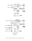
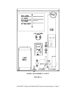
1.8.2 Zero/span valves
The Zero/Span Valve option consists of three stainless steel solenoid valves mounted
inside the Analyzer connected to admit sample gas or customer-generated zero air or span
gas.
The valves are controlled from the front panel push-buttons, the auto-timer via the
RS-232 interface, or by remote contact closure.
A Zero air manifold should supply gas in excess of the 800 cc/min +
10% demand of the
Analyzer. The zero manifold should be connected at the IZS/Zero Air fitting on the rear
of the Analyze and should be vented to the outside atmosphere.
A Span gas manifold can be connected to the analyzer in either of two ways.
1. If it is desired to use span gas directly from a pressurized source (e.g. a gas
cylinder) the connection can be made directly to the Pressure Span port on
the analyzer rear panel. In this case the Vent/Span port at the rear panel
should be vented to a suitable exhaust manifold at ambient atmosphere
pressure. The pressure regulator on the gas source (cylinder should be
sent to provide 30-35 PSI delivery pressure.
2. If it is desired to use span gas from a source which delivers gas at
atmosphere pressure (e.g. a calibrator), the span gas manifold should be
connected at the Vent/Span port at the Analyzer's rear panel, and the
Pressure/Span port should be capped.
P/N 02163G1 Teledyne API Model 300 CO Analyzer Instruction Manual - Page 20