


8 Exit Terminator
A circuit that is normally connected to a push
button outside the protected premises, which
can be used to finally set the system or area.
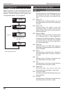
9 Keypoint
A circuit that may be connected to a keyswitch
to allow setting and/or part-setting of the
system. The keypoint circuit can only be used
with the standard hard-wired circuits.
The Keypoint circuit has two groups of
attributes. The first group of attributes controls
which group is set/unset when the circuit is
switched between “Healthy” and “Active”. The
second group of attributes controls which
group is set/unset when the circuit is switched
between “Healthy” and “Shorted”.
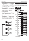
When programming the Keypoint circuit the
eight standard attributes are not available,
instead the attributes are used to select the
Key Point operation as follows:
[1] Full Set Mode - “Healthy” to “Active”.
[2] Part Set Mode A - “Healthy” to “Active”.
[3] Part Set Mode B - “Healthy” to “Active”.
[4] Part Set Mode C - “Healthy” to “Active”.
[5] Full Set Mode - “Healthy” to “Shorted”.
[6] Part Set Mode A - “Healthy” to “Shorted”.
[7] Part Set Mode B - “Healthy” to “Shorted”.
[8] Part Set Mode C - “Healthy” to “Shorted”.
Circuit Attributes
Each circuit type can have one or more attributes
assigned to it to alter its operation. The following
circuit attributes can be programmed:
1 Access
Circuits programmed with this attribute are
automatically isolated during the entry
procedure to allow a “walk through” route for
the user to access the remote keypad. The
“Access” attribute can only be assigned to
Night and Final Exit circuit types.
2 Double Knock
Circuits programmed with this attribute will only
cause an alarm condition if:
a) The circuit is activated twice within the
Double Knock window (this time may be set in
the System Timers menu).
b) The circuit remains active for the whole
duration of the Double Knock window. The
“Double Knock” attribute can only be assigned
to Night, 24hr and Auxiliary circuit types.
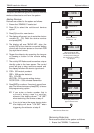
3 Test
Circuits with this attribute will be disabled from
the system for the period set by the “Test Time”
(see System Timers). If the circuit is activated
during this period the activation will be logged
and the user is informed of the circuit failure
when trying to set the system. The test fail
message may only be cleared with the
Engineers passcode. If at the end of the test
period no activations have occurred the
circuit is automatically removed from test and
behaves as normal. The test period is initiated
by entering the Engineers passcode. The “Test”
attribute can only be assigned to Night, 24hr,
PA Silent, PA Audible, Fire, Auxiliary, PSU Battery,
PSU Fuse and PSU Power circuit types.
4 Omittable
Circuits with this attribute are allowed to be
omitted by the user when setting the system.
The “Omit” attribute can only be assigned to
Night, 24hr, Auxiliary, PSU Battery, PSU Fuse and
PSU Power circuit types.
5 Reset
This attribute is normally assigned to a circuit
that is connected to a vibration or smoke
detector, so that during the “Detector Reset”
period the circuit is not monitored. The “Reset”
attribute can only be assigned to Night, 24hr,
Fire and Auxiliary circuit types.
6 Monitored
Circuits with this attribute will activate the
"T imed Ou tput" w hen t rigge red. Th e
“Monitored” attribute can only be assigned to
Night, 24hr, Fire, Auxiliary and Final Exit circuit
types.
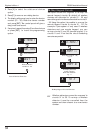
7 Entry
Circuits with this attribute will initiate the entry
procedure when the system is part-set and
respond as normal when full set. This attribute
must be assigned to all circuits that are
required to initiate the entry procedure in the
part-set condition. The “Entry” attribute can
only be assigned to Night, 24hr and Final Exit
circuit types. When assigned to a 24 Hour
circuit type, the circuit can be used to initiate
the entry procedure. Once the system is unset
the 24 hour will revert to normal operation.
27
TS690R Installation Manual Engineer’s Menu 1