


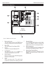
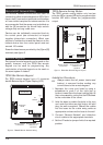

Remote/LEC Network Wiring
The Remote Network connections are used for
connecting either remote keypads or LECs. Each
device has 5 connection terminals and therefore
a 6 core cable is required for interconnection. It is
recommended that the spare core is doubled up
with the [B] connection as this will help reduce
voltage drop on long cable runs.
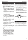
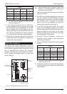
Devices can be individually connected back to
the control panel (star connection) or looped
together (daisy-chain connection). Which ever
method of connection is used the distance to the
furthest device from the control panel must not
exceed 100 metres.
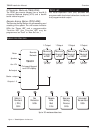
Power for detectors are provided by the [A] and [B]
terminals, see figure 5.
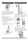
Remote Keypads
Two types of remote keypads can be used on the
system, however, only the TS790 Star remote
keypad can be used for programming. Any
combination of remote keypad can be used on
the same system if desired.
TS790 Star Remote Keypad
The TS790 remote keypad has a 8 character
backlit Starburst Liquid Crystal Display (LCD).
TS700 Remote Arming Station
The TS700 remote arming station only has two
indicator LED's, a power LED and a programmable
function LED which follows the programmable
output.
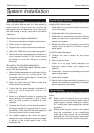
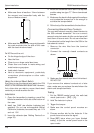
Installation Procedure.
☞
Always ensure that all power (mains and
battery) is removed before making any
connections to the remote keypad.
1. Separate the cover and base by using a
screwdriver to push 2 of the clips (top or
bottom) inward from the base indents, then lift
the cover assembly, noting that the PCB is fixed
to the under side of the cover.
2. Hold the base in position (keyhole to the top)
and mark the three securing holes, drill and
plug the wall as required. Pass all the cables
into the base via the cable entry points as
appropriate and secure the base to the wall.
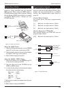
3. Connect “Remote Network” and detection
circuit cables to the appropriate terminals.
4. Set the I/D selector jumper link to the required
position:
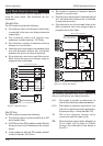
12
System Installation TS690R Installation Manual
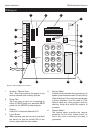
Programmable output
switched -ve
@ 100mA
Remote network
connections
= Disabled
2 Detection
circuits
'ENT'
Key
Disable
WARD SOUNDER
CONTROL
I/D
Selector
Tamper
Switch
A B
REMOTE
I/D
1
2
3
4
ENG
C D E
O/P-
LCD Module
Figure 6. TS690R Remote Network Wiring
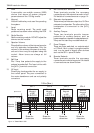
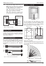
Tamper
Switch
2 detection
circuits
Programmable output
switched -ve
@100mA
I/D
Selector
A B
REMOTE
I/D
1
2
3
4
DISABLED
DISABLED
'ENT' KEY
ENG
C D E
O/P-
Remote network
connections
Figure 7. TS790 Star Remote Keypad Layout