


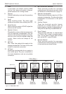
Hard Wired Detection Circuits
Detection circuits from remote keypads or LECs
must be hard wired. Two methods can be
employed:
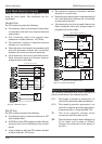
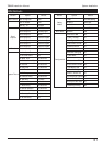
Double Pole
The DP method requires the following:
l
The detector alarm and tamper contacts are
connected to the zone and tamper terminals
respectively.
l
The combined alarm and tamper loop
resistance must be less than 100 Ohms.
l
The maximum number of detection devices
allowed in a circuit is ten.
l
Normally open devices such as pressure pads
and exit terminator buttons are connected
between the zone and tamper terminals.
l
If the detection circuit is not used links can be
fitted across the zone and tamper loops or
programmed as Not Used.
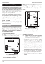
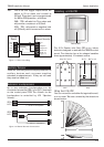
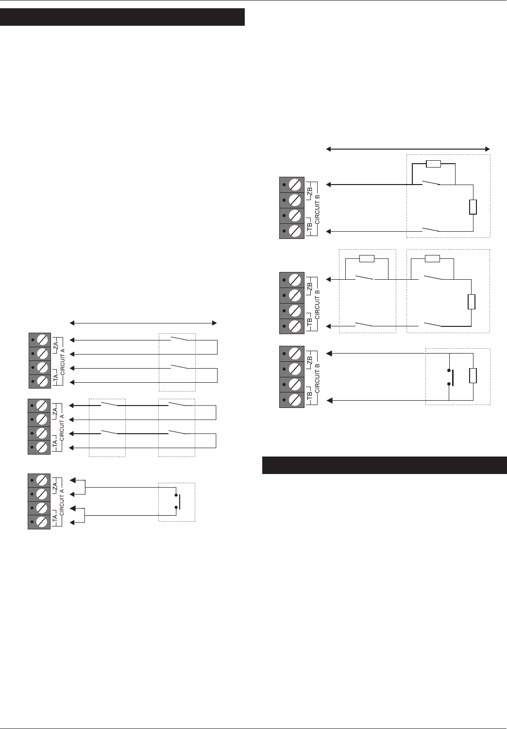
End Of Line
The EOL method requires the following:
l
The detector alarm contacts must have a 4K7
shunt resistor fitted.
l
A 2K2 End of Line (EOL) resistor must be fitted at
the point in the circuit furthest from the control
panel.
l
Loop resistance with the EOL resistor shorted
must be less than 100 Ohms.
l
The maximum number of detection devices
allowed in a circuit is ten.
l
Normally open devices such as pressure pads
and exit terminator buttons are connected
across outer terminals
l
If the detection circuit is not used links can be
fitted across the zone and tamper loops or
programmed as Not Used.
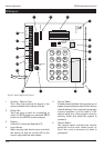
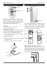
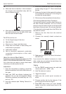
External Sounder Connections
The following terminals have been provided to
allow connections to an external sounder:
H/O - This is used to provide a permanent -ve
hold off to external sounders, strobes etc.
H/O + This is used to provide a permanent +ve
hold off to external sounders, strobes etc.
It is protected by a 1 Amp fuse (Bell 12V).
TR - This is the negative tamper return
connection from the siren or bell.
STB - This is the strobe output which will switch to
0V on alarm and is rated at 500mA.
Connect the other side of the strobe to
the H/O +.
14
System Installation TS690R Installation Manual
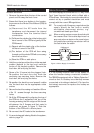
Alarm
Tamper
Alarm
Tamper
Max. 10 devices per circuit
Wiring N.O. devices (Exit Terminators)
Alarm
Tamper
500 meters or 100 Ohms
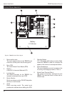
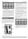
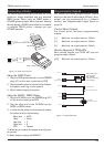
Figure 9. TS700 LEC Layout
500 meters or 100 Ohms
Alarm
Alarm
Tamper
Max. 10 devices per circuit
Wiring N.O. devices (Exit Terminators)
Tamper
4K7 = Yellow, Violet, Red
2K2 = Red, Red, Red
Alarm
Tamper
4K7
4K7
4K7
2K2
2K2
2K2
Figure 10. Double Pole Wiring