


GT INSTALLATION AND OPERATION INSTRUCTIONS Page 9
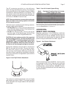
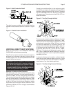
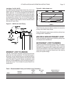
Figure 13 - Wall Penetration Detail
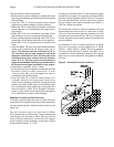
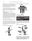
The debris screen provided with the boiler must be
installed in the concentric terminal as shown in Figure
14.
Figure 14 - Debris Screen Installation
VERTICAL DIRECT VENT SYSTEMS
Read the information in the GENERAL VENTING
GUIDELINES section before proceeding.
The GT can be vented vertically directly through the
building’s roof or through a dormant chimney used as
a chase, Figures 15 & 16. All roof penetrations must be
properly fl ashed and sealed.
WARNING: Under no conditions, shall this boiler
vent gases directly into a masonry chimney
nor can an active chimney be used as a chase.
Failure to comply with this warning can result in
excessive levels of carbon monoxide which can
cause severe personal injury or death!
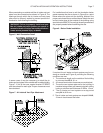
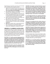
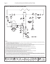
Separate Air Intake and Vent Terminals
The discharge of the vent terminal must point away
from the pitch of the roof. The vent terminal must be a
minimum of 18 in, 457 mm, above the air inlet terminal.
The vent terminal must also be 24 in, 610 mm, above
any roof surface within a horizontal distance of 10 ft,
3 m. The air inlet terminal must always be a minimum
of 12 in, 305 mm, plus the snow allowance above
any surface that will support snow, however a snow
allowance of 24 in, 610 mm, is highly recommended
Figures 15 & 16.
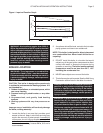
Consult your weather office for the maximum typical
snowfall for your region. For example, in Boston MA the
maximum typical snowfall is 12 in, 305 mm. Therefore
the inlet must be 24 in, 610 mm, above any surface that
will support snow. The exhaust must be 42 in, 1067 mm,
above this surface.
Figure 15 - Two Pipe Through the Roof
The horizontal centerline distance between the inlet
and exhaust terminals must be a minimum of 4 in,
102 mm. If the horizontal distance between the inlet
and exhaust is more than 12 in, 305 mm, increase
the vertical separation by the same amount. For
example, if the horizontal separation is 24 in, 610 mm,
a minimum vertical separationof 30 in, 762 mm,
is required, 18 in, 457 mm, + 12 in, 305 mm, = 30 in,
762 mm. If the horizontal distance is greater then
6 ft, 1.8 m no additional vertical spacing is required.
The vertical separation is never required to be greater
then 36 in, 914 mm.
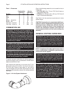
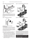
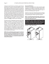
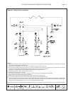
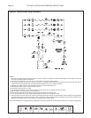
A dormant chimney can be used as a chase through
which the air intake and vent pipes can be run, Figure
16. The chimney must not be connected to a fi replace,
water heater or any other heating appliance.
Figure 16 - Two Pipe Using Dormant Chimney