


GT INSTALLATION AND OPERATION INSTRUCTIONSPage 18
Safe lighting and other performance criteria were met
with the gas manifold and control assembly provided on
the boiler when the boiler underwent tests specifi ed in
ANSI Z21.13/CSA 4.9. All gas connections MUST be leak
tested before putting the boiler into operation.
WARNING: Never use an open fl ame to test for
gas leaks. Always use an approved leak detection
method. Failure to comply with this WARNING
could result in an explosion!
Table 4 - Gas Pipe Capacity
Nominal
Pipe Length
Iron Pipe 10' 20' 30' 40' 50' 60' 80' 100' 150'
Size
Gas Pipe Capacity (ft
3
/hr)
3/4" 278 190 152 130 115 105 90 79 64
1" 520 350 285 245 215 195 170 150 120
1 1/4" 1050 730 590 500 440 400 350 305 250
1 1/2” 1600 1100 890 760 670 610 530 460 380
Note: Maximum pipe capacity in ft
3
/hr is based on a 0.60 specifi c gravity
gas at a pressure of 0.5 psig and a 0.3" WC pressure drop.
Table 5 - Equivalent Pipe Length Chart
Nominal
Type of Pipe Fitting
Iron
90°
Tee Gate Valve
Gas Cocks
Pipe (branch fl ow) (full port)
Size
Equivalent length of pipe fi ttings in feet
3/4" 2.06 4.12 0.48 1.25
1" 2.62 5.24 0.61 1.60
1 1/4" 3.45 6.90 0.81 2.15
1 1/2" 4.02 8.04 0.94 2.50
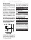
Whenever the gas supply piping is pressure tested the
boiler gas controls must be protected. If the test pressure
is equal to, or less than 1/2 psi, 3.5 kPa, isolate the boiler
by closing it’s manual shut off valve, see Figure 27. If the
test pressure is greater than 1/2 psi, 3.5 kPa, disconnect
the boiler and it’s individual shut-off valve from the gas
supply piping.
WARNING: Failure to protect the gas valve from
excessive pressure can damage the gas valve
which can cause a fi re or explosion!
GAS SUPPLY PIPING
The GT hot water boiler comes from the factory ready
to be piped to the gas supply. The National Fuel Gas
Code, ANSI Z223.1/NFPA 54 and local codes for gas
piping requirements and sizing must be followed. If for
any reason the boiler is not for the type of gas available
at the installation site, call the nearest Smith distributor
to resolve the problem.
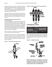
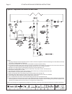
Figure 27 depicts the proper way to connect the boiler to
the gas supply piping. The manual shut-off valve MUST be
installed in the supply piping. It should be approximately
5 ft, 1.5 m, above the fl oor. Provide a sediment trap/drip
leg at the bottom of the vertical section of the gas supply
pipe. A ground joint union should be installed between
the boiler gas controls and the supply piping. Each of
these items is needed to ensure long life and ease of
servicing. Always use a pipe sealant that is suitable for
use with LP gas. Flexible gas piping is recommended if
accepted by the local codes. Make sure the gas piping
doesn’t hinder boiler access.
CAUTION: Always use a wrench on the gas valve
body when making gas connections to it. Never over-
tighten the piping entering the gas valve body or the
gas valve will be damaged voiding the warranty!
CAUTION: The gas piping must be properly supported
by the building structure and not by the boiler or the
gas valve will be damaged voiding the warranty!
Figure 27 - Gas Supply Piping
Table 4 should be used to ensure that the gas supply
piping is sized properly. If more than one appliance is
supplied by the same supply pipe, the piping must be
sized based on the maximum possible demand. Do not
neglect the pressure drop due to pipe fi ttings. Table 5
should be used in conjunction with Table 4 to ensure that
the gas supply piping is sized properly.