


GT INSTALLATION AND OPERATION INSTRUCTIONS Page 13
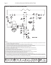
Table 3 - Recommended Primary and Indirect Loop Circulators
Minimum Max. Temp. Minimum Primary &
Restriction Flow Rise Indirect Pump Size
Model Head Loss GPM, L/s °F, °C
B&G Grundfos Taco
GT-150 7 ft at 6 GPM, 2.1 m at 0.4 L/s 6, 0.4 45, 25 NRF-33 UP 26-64 0010
GT-200 10 ft at 8 GPM, 3 m at 0.5 L/s 8, 0.5 45, 25 PL-36 UP 26-99 0011
GT-400 10 ft at 20 GPM, 3 m at 1.25 L/s 13, 0.8 57, 45 PL-36 UP 26-99 0011
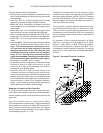
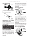
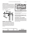
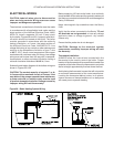
Low Water Cut Off, LWCO
If a LWCO is used ensure that the water line of the “Low
Water Cutoff” is at least 6 in, 152 mm, above the top of the
boiler, Figure 21. It is recommended that the LWCO be
situated so that it can be tested without removing water
from the boiler. Tri-cocks and a gauge glass are highly
recommended. Valves shall not be installed between
the LWCO and the boiler. Use an air vent if installed as
per our diagram to be used as a vacuum breaker and to
eliminate air upon fi lling.
Figure 21 - LWCO & Air Vent Piping
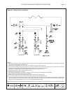
PRIMARY LOOP PLUMBING
This low mass boiler requires a continuous minimum
water fl ow for proper operation. The heat exchanger in
this boiler is more restrictive than a conventional boiler.
The system pump must be sized to overcome the head
loss of the boiler, Figure 22. Greater consideration must
be given to the capabilities of the circulating pump(s) in
the primary-loop. This includes the pump used for an
indirect tank.
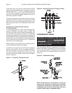
Figure 22 - Boiler Head Loss
Table 3 lists the recommended circulators for use as the
primary and indirect loop pumps.
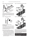
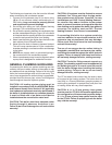
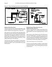
Figure 23 shows the proper way to plumb a primary loop
for single boiler installations.
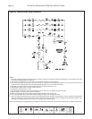
MULTIPLE BOILER PRIMARY LOOP
Figure 24 shows the proper way to plumb a primary loop
for multiple boiler installations.
SECONDARY LOOP PLUMBING
Figures 25 and 26 show some typical primary/ secondary
piping systems. It is the responsibility of the installing
contractor to determine which system best meets the
need of the installation. Contractor modifi cations to these
instructions may be required, based upon the existing
piping and system design.
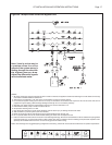
0
20
40
60
2 4 6 8 10 12 14 16 18 20 22 24 26 27
GPM us
daeH fo teeF
GT-150 GT-200 GT-400