


GT INSTALLATION AND OPERATION INSTRUCTIONSPage 10
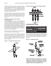
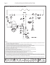
Figure 18 - Multiple Concentric Through the Roof
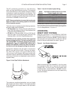
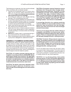
CONDENSATE DRAIN
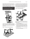
WARNING: The condensate siphon must be
connected to the boiler per the following
instructions or combustion gases will enter
the room. This can result in excessive levels
of carbon monoxide which can cause severe
personal injury or death!
This unit produces water as a byproduct of combustion.
Much of this water condenses on the heat exchanger
and in the venting system. Condensate must be drained
from the boiler into a household drain as shown in
Figure 19.
Figure 19 - Condensate Piping
NOTE: Check with your municipality, or local gas
company to determine if disposal of untreated
combustion condensate is permitted. If not, the
condensate will have to be neutralized with lime
crystals, marble chips or phosphate chips.
Install and seal a rain cap over the dormant chimney
opening to prevent water from entering the building.
Use only ABS, PVC
sch.40
, CPVC, or AL294C pipe for the
air inlet and vent systems as stated previously. Ensure
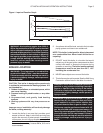
that the air inlet and vent system lengths are within the
maximums specifi ed in Table 2.
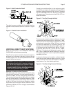
The debris screens provided with the boiler must be
installed in both the air intake and vent terminals. Install
the screens in the outer most opening then glue a 1 in,
25 mm, length of pipe into the opening to retain them,
Figure 9.
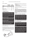
Concentric Air Intake and Vent Terminal
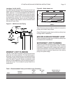
GT-150 & 200 Only
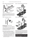
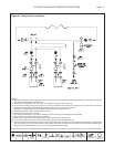
If a concentric terminal is used it must be Smith part
number GT-82666 or York part number 1CT0303. The
concentric terminal must be located at least 24 in, 610
mm, above the normal snow line, Figure 17. The building
structure must support the air inlet and vent systems. All
roof penetrations must be properly fl ashed and sealed. A
dormant chimney can be used as a chase through which
the air intake and vent pipes can be run. All previous
instructions and warnings apply.
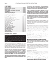
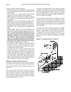
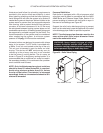
When terminals from multiple boiler installations exit a
roof the following conditions must apply:
If limited to two terminals the horizontal centerline
distance must be 4 in, 102 mm or greater than 24 in,
610 mm, to prevent flue gas recirculation. For more
than two terminals located along a given plane, the
centerline distance between them must be 24 in,
610 mm, Figure 18.
Figure 17 - Concentric Through the Roof