


GT INSTALLATION AND OPERATION INSTRUCTIONS Page 19
ELECTRICAL WIRING
CAUTION: Label all wires prior to disconnection
when servicing controls. Wiring errors can cause
improper and dangerous operation!
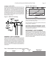
The electrical connections to this boiler must be made
in accordance with all applicable local codes and the
latest revision of the National Electrical Code, ANSI/
NFPA-70. Install a separate 120 volt 15 amp circuit
for the boiler, Figures 28 and 29. A properly rated shut-
off switch should be located at the boiler. The boiler
must be grounded in accordance with the authority
having jurisdiction, or if none, the latest revision of
the National Electrical Code, ANSI/NFPA-70. Line
voltage fi eld wiring of any controls or other devices must
conform to the temperature limitation of type T wire
at 95°F, 35°C, above room temperature.Use copper
conductors with a minimum size of #14 awg. Low voltage
wiring must not be less than #18 awg with a neoprene,
thermoplastic or other equivalent insulation having a
minimum insulation thickness of 0.012 in, 3 mm.
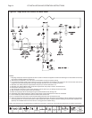
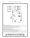
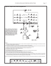
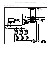
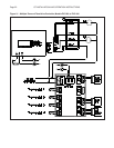
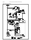
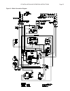
Schematic and ladder diagrams of the boilers wiring are
shown in Figures 33 & 34.
CAUTION: The contact capacity of outputs C
1
or A
p
is 3 amps with a maximum inrush of 6 amps. If the
amp draw of the pumps exceeds these maximums,
a pump controller, or isolation relay must be used
to prevent damage to the boiler. Damage caused by
improper wiring will void the warranty!
Before supplying 120 volts to the boiler, do a continuity
check between all the wires and the ground to make sure
that there are no electrical shorts that could damage the
Sentry 2100 board.
Never use magnetic tip screwdriver near the Sentry
2100.
Verify that the wires connected to the Sentry TC and
AC terminals are not grounded, or have any voltage
applied to them, or voltage to ground - dry contact
closure only.
Ensure that the probe wire is not damaged.
CAUTION: Damage to the electrical system
components caused by improper wiring will void
the warranty!
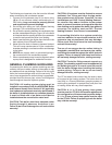
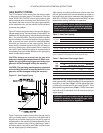
Thermostat Installation
ALWAYS follow the instructions included with the
thermostat to be used to control the boiler. Proper
location of the thermostat will ensure effi cient trouble-free
operation of the boiler. Mount the thermostat to an inside
wall at a height approximately fi ve feet above the fl oor.
Avoid placing the thermostat in areas that will not provide
an accurate measurement of the room temperature.
Locating the thermostat behind a door, in an alcove,
close to a source of thermal radiation or in a drafty area
will cause poor or sporadic heating.
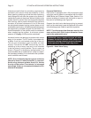
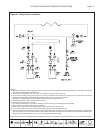
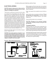
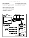
Figure 28 - Basic Heating System Wiring