


GT INSTALLATION AND OPERATION INSTRUCTIONSPage 30
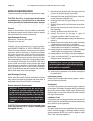
The gas supply pressure to the boiler while running
at maximum rate must be between 4 to 9 in, 102 to
229 mm, W.C. for natural gas installations; 9 to 12 in, 229
to 305 mm, W.C. for propane installations. This pressure
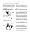
can be measured on the gas valve using a manometer,
Figure 41 or 42. Ensure that the regulator is capable of
maintaining this pressure under all operating conditions.
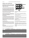
The gas valve is also equipped with a manifold pressure
port, Figure 41 or 42.
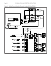
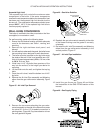
Figure 41 - Gas Valve Layout, GT-150 & 200
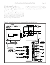
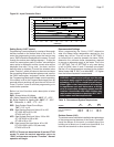
Figure 42 - Gas Valve Layout, GT-400
Ignition System
A. Connect a manometer to the line pressure port
shown in Figure 41 or 42. Make sure that the gas
supply piping has been purged of air and that all
gas joints up to the gas valve have been thoroughly
checked for leaks. Wait at least fi ve minutes for any
gas to dissipate before turning on the electrical
power.
B. Read, understand and follow the operating
instructions below.
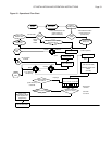
C. Raise the thermostat at least 5 degrees above the
room temperature. The boiler should enter the pre-
purge mode before energizing the silicon carbide
igniter. Once the igniter is hot, the main gas valve
will open and the burner should light. If the burner
fails to light the system will make three more ignition
attempts. If the burner has not lit after the last
ignition try, the gas valve will close and the system
will go into lock out. DO NOT attempt to reset the
system until the ignition system has been inspected
and the problem resolved. Once the problem has
been resolved and 5 minutes have passed since
the last ignition attempt, reset the system by turning
the thermostat to it’s lowest setting and then back
to where it was or by momentarily interrupting the
electrical power to the boiler.
D. With the burner in operation close the manual shutoff
valve in the gas supply line. As soon as the burner
fl ame goes out, open the manual shutoff valve. A
normal ignition sequence should take place.
E. With the burner in operation, interrupt the power to the
control circuit by lowering and raising the thermostat.
A normal ignition sequence should follow.
F. To test the ignition safety shutoff device, close the
manual shutoff valve in the gas supply line. Within 6
seconds of main burner fl ame extinction, the main
gas valve solenoid should close with an audible noise.
The igniter should glow and make three attempts at
ignition. After unsuccessfully attempting to light the
burner the ignition module should lock out.
Input Screw
Manifold Pressure
Line Pressure