


GT INSTALLATION AND OPERATION INSTRUCTIONS Page 33
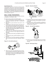
Gas Pressure Adjustment
Optimum results are obtained when the boiler is operated
at its full input rating. If adjustment is necessary the
following steps must be followed:
1. Connect a fl ue gas analyzer to the vent pipe.
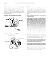
2. Rotate the input adjustment screw clockwise to
decrease the manifold pressure, counterclockwise
to increase it, Figure 41 or 42. The input screw on
the GT-150 & 200 is a multi turn needle valve. From
fully open to fully closed is approximately 17 turns.
A typical adjustment is 0 to 1 turn for natural gas,
0 to 3 turns for LP. The input screw on the GT-400
turns a geared ball valve with a 4 to 1 ratio. Two turns
will take the valve from fully open to fully closed.
0 to 1/4 turn is a typical adjustment. Never force
the input adjustment screw or the gas valve will be
damaged!
3. For natural gas the CO
2
reading should fall between
8% and 9.5% with a CO reading of less than 175
ppm air free. For LP gas the CO
2
reading should fall
between 9% and 10.5% with a CO reading of less
than 175 ppm air free.
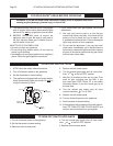
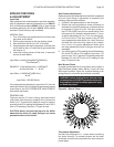
Main Burner Flame
A properly adjusted main burner fl ame will produce a
tight blue fl ame pattern about 1/2 in, 13 mm, tall from
the burner’s surface, Figure 44. A yellow fl oating or tall
stringy fl ame is not normal and must be corrected.
WARNING: Yellow, fl oating fl ames indicate a lack
of combustion air. DO NOT operate the boiler until
the problem is solved or severe personal injury
or death may occur!
Figure 44 - Burner Flame
Thermostat Adjustment
Set the heat anticipator to 1.1 amps when controlling
the boiler directly. For zoned systems set the heat
anticipator to match the amp draw of the zone valves or
pump relays.
BOILER CHECKING
& ADJUSTMENT
Input Rate
Gas appliances are rated based on sea level operation
with no adjustment required at elevations up to 2000 ft,
610 m. At elevations above 2000 ft, 610 m, input ratings
should be reduced by 4% for each 1000 ft, 305 m, above
sea level. Check the input rate as follows:
NATURAL GAS:
1. Turn off all other gas appliances that use the same
gas meter as the boiler.
2. Call the gas company for the gas heating value.
3. Start the boiler and let it run for 15 minutes.
4. Using the gas meter and a stopwatch, clock the time
that it takes to burn 10 cubic feet of gas and divide
the time by 10.
5. Insert the heating value and the time, in seconds,
into the formula below.
Input Rate = Heating Value(Btu/ft
3
)(3600 s/hr)
Flow Rate(s/ft
3
)
EXAMPLE: If the heating value = 1000 Btu/ft
3
and the fl ow rate = 18 s/ft
3
Input Rate = (1000 Btu/ft
3
)(3600 s/hr)
18 s/ft
3
Input Rate = 200,000 Btu/hr
If the computed rate deviates by more than 5% from the
rated input value of the unit adjust the gas valve pressure
according to the GAS PRESSURE ADJUSTMENT
instructions that follow.
PROPANE GAS:
The input rate for LP units is factory set based on the
orifi ce size. Use the factory supplied kit to convert the
boiler to LP. A combusiton analyzer must be used to
ensure that the CO
2
reading falls between 9% and 10.5%
with a CO reading of less than 175 ppm air free.
CAUTION: Never increase the input to the boiler
above that for which it is rated. Doing so can cause
premature failure of the boiler!