


GT INSTALLATION AND OPERATION INSTRUCTIONSPage 20
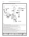
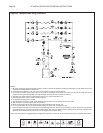
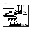
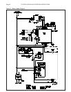
Multiple 4 Wire Zone Valves
Figure 30 shows the basic multiple zoned system uses
normally closed four (4) wire zone valves. This wiring
system is used with the piping shown in Figure 26.
When there is a call for heat the room thermostat closes
the circuit to the zone valve motor, thus opening the zone
valve. When the zone valve is opened, the end switch
closes the circuit between terminals T and C on the
Sentry 2100 control. The Sentry 2100 provides power to
the primary and secondary pumps via terminal C
1
. Once
these pumps are on, the burner fi res.
Once the room thermostat is satisfi ed, it breaks power
to the zone valve motor. The end switch opens the circuit
between terminals T and C shutting down the pumps
and the burner.
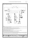
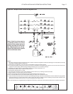
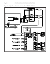
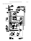
Multiple Zones w/ Taco Valve Controller
Models ZVC403 to ZVC 406
Figure 31 shows the basic multiple zoned system using
normally closed 2, 3 or 4 wire Taco zone valves. This
wiring system is used with the piping as shown in Figure
26.
When there is a call for heat the room thermostat closes
the circuit between the TT terminals on the Taco zone
controller. The controller energizes the appropriate zone
valve and closes the circuit between terminals T and C on
the Sentry 2100 control. The Sentry 2100 provides power
to the primary and secondary pumps via terminal C
1
.
Once these pumps are on, the burner fi res.
Once the room thermostat is satisfi ed, it breaks power
to the zone valve motor. The end switch opens the circuit
between terminals T and C shutting down the pumps
and the burner.
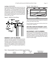
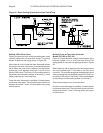
Figure 29 - Basic Heating System and Indirect Tank Wiring