


GT INSTALLATION AND OPERATION INSTRUCTIONS Page 5
The GT condensing gas boiler is a high efficiency
boiler utilizing induced power venting. It is designed
to be vented directly to the outdoors using the venting
methods and materials detailed in this section. The
vent system must be both gas tight and watertight. All
horizontal vent piping must be sloped back to the boiler
a minimum of 1/4 in/ft, 21mm/m of vent.
NOTE: Steps must be taken to ensure that condensate
does not collect in the venting system or the boiler
will not operate properly.
This boiler may be vented using the following materials,
but local codes must be followed:
• GT150 & 200: 3 in, 76 mm, PVC Sch.40 solid core
pipe, CPVC Sch.40 pipe, AL29-4C Flex Stainless Vent
or AL29-4C Rigid Stainless Vent.
• GT-400: 4 in, 102 mm or 6 in, 152 mm, PVC Sch.40
solid core pipe, CPVC Sch.40 pipe, AL29-4C Flex
Stainless Vent or AL29-4C Rigid Stainless Vent.
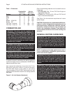
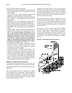
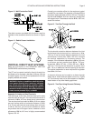
CAUTION: All vent systems must be fully supported
by the building structure. The vent connection and
vent piping MUST be perfectly aligned to the boiler
connection, Figure 3. It MUST NOT APPLY ANY
WEIGHT OR LATERAL FORCE TO THE FLUE BOX or
the fl ue box will be damaged voiding the warranty!
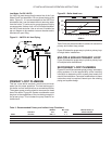
Appropriate adapters must be used to increase the
2 in, 51 mm vent collar to 3 in, 76 mm at the boiler,
GT-150 & 200, Figure 3. On the GT-400 the 4 in,
102 mm long 4 inch diameter ABS pipe provided with
the boiler must be inserted into the exhaust connection
on the top of the boiler and tightened in place with the
supplied clamp.
Figure 3- Vent Pipe To Boiler Attachment
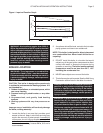
The maximum combined equivalent vent and intake
pipe lengths are listed in Table 2. The length specifi ed
is the equivalent vent length added to the equivalent
intake length.
Table 2 - Vent & Air Intake System Sizing
Model Equivalent Combined Vent & Air Intake
Number System Length (see note)
GT-150 105 ft, 32 m
GT-200 105 ft, 32 m
GT-400 4" - 30 ft, 9 m 6" - 65 ft, 20 m
PGT-150 50 ft, 15 m
PGT-200 50 ft, 15 m
PGT-400 4" - 30 ft, 9 m 6" - 65 ft, 20 m
Note: Subtract 5 ft, 1.5 m, for each 90° elbow except for the vent and
air intake elbows. These don’t need to be considered. The length of
the air inlet system must never exceed the length of the vent system.
The vent system length may exceed the air inlet system length by no
more than 20 equivalent ft, 6.1 equivalent m.
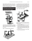
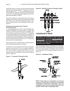
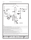
HORIZONTAL
DIRECT VENT SYSTEMS
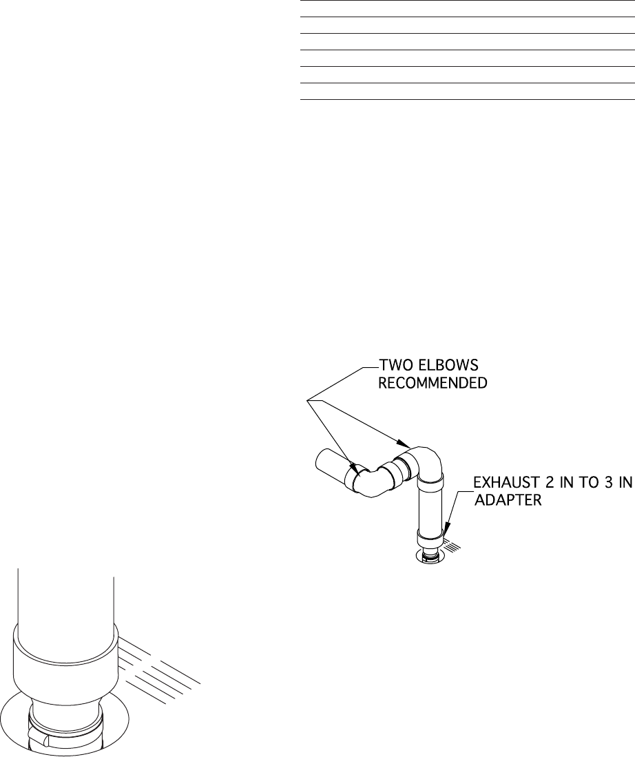
Read the information in the GENERAL VENTING
GUIDELINES section. It is recommended that two
elbows be used, so that the 1/4 in/ft, 21mm/m slope of
the horizontal vent system does not affect the vertical
plumb of the pipe connected to the boiler, Figure 4.
Figure 4 - Vent System Attachment
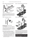
When horizontal vent runs exceed 5 ft, 1.5m, they must
be supported at 3 ft, 0.9 m, intervals with overhead
hangers, 4 ft, 1.2 m for 6" pipe. The vent system must
be pitched down, toward the boiler, 1/4 in/ft, 21mm/m.
of vent. Structural penetrations must be made using
approved thimbles.