


GT INSTALLATION AND OPERATION INSTRUCTIONSPage 16
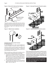
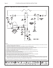
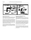
Air Vent
Automatic
Check Valve
Pump
Ball Valve
Drain Valve
(Typ.)
Heating
Load
Differential Pressure
Bypass Valve
Zone
Valve
Expansion
Tan k
Spirotrap
Fine Particulate
Separator
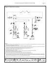
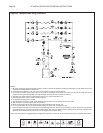
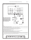
Figure 25 - Multiple Zones Using Circulators
NOTES:
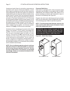
1. All piping and pumps must be supported so that no loads or stresses are applied to boiler heat exchanger. To make boiler service easy
use Unions or fl exible Vibration Isolation Kit.
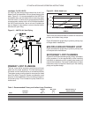
2. This boiler is provided with a 1/8" vent that is not intended for continuous system venting.
3. For continuous system venting use a cast iron air scoop, for excessive air conditions use a Spirovent. Do not fi re boiler until all air is
purged from the system piping. Heat exchanger damage caused by air is not covered by warranty.
4. See Table 3 for boiler pump fl ow requirements. This pump is wired to terminals C1-L2.
5. Indirect Water Heater pump is wired to terminals AP-L2.
6. Set pressure reducing valve to 12 PSI.
7. Use 30 psi relief valve max. Locate where discharge will not cause injury or damage. Follow local codes.
8. Add an inhibitor to protect system. (CHP from Fernox)
9. Boiler circuit piping must be sized large enough to handle maximum fl ow through unit.
10. Do not operate boiler with service valves closed isolating the boiler from the expansion tank.
11. Failure to follow these instructions will result in heat exchanger damage: All fl ux and contaminants must be fl ushed from piping before
connecting boiler. Do not connect this boiler to older systems with cast iron radiation without installing a fi ne particulate separator. TYP:
Spirotrap Junior Model TDN 125 FT. Do Not use non-oxygen barrier radiant tubing.
Notice: This drawings show suggested piping confi guration and valving. Check with local codes and ordinances for specifi c requirements.