


GT INSTALLATION AND OPERATION INSTRUCTIONSPage 8
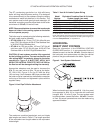
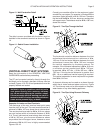
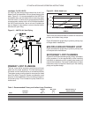
Figure 9 - External Air Intake and Vent Systems
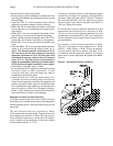
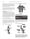
The debris screens provided with the boiler must be
installed in both the air intake and vent terminals. Install
the screens in the outer most opening then glue a 1 in,
25 mm length of pipe into the opening to retain them,
Figure 10.
Figure 10 - Debris Screen Installation
Concentric Air Intake and Vent Terminal
GT-150 & 200 Only
If a concentric terminal is used it must be Smith part
number GT-82666 or York part number 1CT0303. The
concentric terminal must be located at least 12 in, 305
mm, above the normal snow line, Figure 11. Position the
air intake pipe on the top or to the side to prevent rain
from entering the boiler, Figure 13.
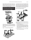
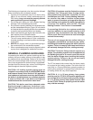
When terminals from multiple boiler installations exit a
common wall the following conditions must apply:
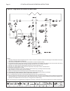
1. If limited to two terminals the horizontal centerline
distance must be 4 in, 102 mm, or greater than
24 in, 610 mm, to prevent flue gas recirculation.
For more than two terminals located along a
horizontal plane, the centerline distance between
them must be 24 in, 610 mm, Figure 11.
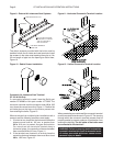
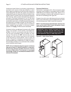
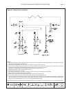
2. If the terminals are located in a vertical plane the
centerline distance between them must be at least
48 in, 1220 mm, Figure 12.
Figure 11- Horizontal Concentric Terminal Location
Figure 12 - Vertical Concentric Terminal Location
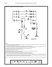
When penetrating an outside wall the concentric terminal
must be constrained as shown in Figure 13. The opening
through which the concentric terminal passes must be
properly sealed to prevent products of combustion from
entering the building. The air intake of the boiler must
be connected to the terminal!
WARNING: Failure to properly install and seal the
concentric terminal can result in excessive levels
of carbon monoxide which can cause severe
personal injury or death!
EXHAUST
USING ONLY 3" PIPE ON
THE 150 & 200 AND 4"
PIPE ON THE 400
INLET
20 FOOT MAX OUTSIDE
SUPPORTS EVERY 24 IN
12 IN ABOVE MAXIMUM
SNOW LINE