


GT INSTALLATION AND OPERATION INSTRUCTIONSPage 12
Understand and follow the plumbing requirements
provided in this section. Keep serviceability in mind
when installing plumbing around the boiler cabinetry.
Install fi ttings that will allow the system to be fl ushed if
needed during annual check-ups. Add an inhibitor to the
system water to prevent lime and magnetite deposits
from forming, and to protect the boiler from galvanic
corrosion. A minimum clearance of 1 in, 25 mm must
be maintained between heating system pipes and all
combustible construction. All heating system piping must
be supported by suitable hangers not the boiler. The
thermal expansion of the system must be considered
when supporting the system. A minimum system
pressure of 12 psig, 84 kPa must be maintained.
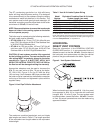
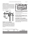
Hot water boilers are designed to operate with airless
water in the system. The GT boiler is provided with
a 1/8 in, 3 mm, air vent located on the top of the unit.
This air vent is intended to vent the boiler on initial
startup. This device will NOT continuously vent air
collecting in the primary loop and is not intended
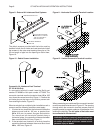
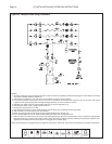
to be the primary venting device. The air scoop as
shown in Figure 21 is the primary venting location. It is
recommended that an additional air scoop be used in
the secondary plumbing. If air continues to be a problem
an air scrubber must be used.
NOTE: Only inhibited propylene glycol solutions
should be used if freeze protection is required.
Avoid using mixtures greater than 30%, unless
the size of the boilers’ circulator(s) is increased
accordingly. Under no circumstances should a 50%
mixture be exceeded.
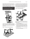
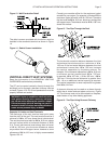
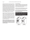
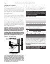
Pressure Relief Valve
Each boiler is equipped with a 30 psi pressure relief
valve that must be piped in accordance with the ANSI/
ASME Boiler and Pressure Vessel Code, Section IV to
prevent scalding of persons with hot liquid or vapor in
the event of a discharge, see Figure 20.
Support the relief valve discharge piping to prevent
strain on the valve body. Leave the open end of the relief
valve discharge pipe visible for periodic inspection.
NOTE: The discharge pipe diameter must be the
same at the relief valve output diameter. Never
restrict the outlet relief valve.
WARNING: Never install any type of valve
between the boiler and the relief valve or an
explosion causing extensive property damage,
severe personal injury or death may occur!
Figure 20 - Relief Valve Piping
Non ASME GT-150 All ASME Models