


GT INSTALLATION AND OPERATION INSTRUCTIONSPage 4
One of the following materials is to be used for the air
intake pipe:
• GT-150 & 200: 3 in, 76 mm, PVC Sch.40 pipe or
Galvanized Steel pipe.
• GT-400: 4 in, 102 mm or 6 in 152 mm, PVC Sch.40
pipe or Galvanized Steel pipe.
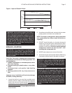
See Table 2 for the maximum equivalent air intake
system length.
CAUTION: Combustion air contaminated with fl uoro-
carbons or other halogenated compounds such as
cleaning solvents, refrigerants, chloride, fl ouride,
bromine or iodine will result in the formation of
acids in the combustion chamber. These acids will
cause premature failure of the boiler voiding the
warranty!
GENERAL VENTING GUIDELINES
WARNING: The vent installation must be in
accordance with Part 7, Venting of Equipment, of
the latest revision of the National Fuel Gas Code,
ANSI Z223.1/NFPA 54 applicable provisions of
the local building codes. Improper venting can
result in excessive levels of carbon monoxide
which can result in severe personal injury or
death!
NOTE: Compliance with code requirements doesn’t
insure a satisfactory installation; good common
sense must also be applied.
WARNING: Each boiler must have it’s own vent
system. Common positive pressure vent systems
are not to be used! Improper installation can
result in excessive levels of carbon monoxide
which can cause severe personal injury or
death!
WARNING: Field supplied piping and fittings
are required to complete installation. The
combustion air and vent pipe and fi ttings must
conform to ANSI and ASTM standard D1785
for schedule 40 PVC, D2665 for PVC-DWV, and
D2661 for ABS-DWV. Pipe cement and primer
must conform to ASTM standard D2564 for PVC
or D2235 for ABS. Improper venting can result in
excessive levels of carbon monoxide which can
result in severe personal injury or death!
Table 1 - Clearances
Combustible Service
Clearance Clearance
Surface in mm in mm
Front 0 0 24 610
Back 0 0 0 0
Sides 0 0 12 305
Top 0 0 12 305
Bottom - 150 & 200 0 0 12 305
Bottom - 400 0 0 0 0
Flue Pipe - enclosed 2 51 n/a n/a
Flue Pipe - in free air 0 0 n/a n/a
COMBUSTION AIR
WARNING: This boiler must be supplied with
combustion air in accordance with Section 5.3,
Air for Combustion & Ventilation, of the latest
revision of the National Fuel Gas Code, ANSI
Z223.1/NFPA 54 and all applicable local building
codes. Failure to provide adequate combustion
air for this boiler can result in excessive levels
of carbon monoxide which can result in severe
personal injury or death!
WARNING: Never operate this boiler unless the
air intake is connected to the outdoors. Failure to
comply with this warning can result in excessive
levels of carbon monoxide causing severe
personal injury or death!
WARNING: Each boiler must have it’s own intake
air system. Common intake air systems are not
to be used! Improper installation can result in
excessive levels of carbon monoxide which can
cause severe personal injury or death!
To operate properly and safely this boiler requires a
continuous supply of air for combustion. NEVER store
objects around the air inlet!
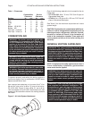
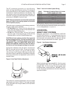
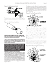
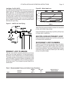
Use appropriate adapters to increase the 1
1
⁄
2
in,
38 mm air inlet collar to 3 in, 76 mm at the boiler,
GT-150 & 200, Figure 2. Use a 2 in, 51 mm to 4 in,
102 mm adapter on the GT-400. Terminate the air inlet
system per the instructions found in the venting sections
that follow.
Figure 2 - Air Inlet System Attachment