


GT INSTALLATION AND OPERATION INSTRUCTIONS Page 35
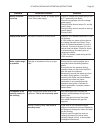
Aquastat High Limit
The aquastat high limit controls the maximum water
temperature in the boiler. If the water temperature
reaches the set temperature before the demand for heat
has been met, the aquastat high limit should shut the
burners off. The outlet water temperature should never
exceed 220°F, 104°C. If the aquastat high limit fails to
function properly replace it.
WALL HUNG CONVERSION
This boiler is certifi ed to be either mounted on the fl oor
as supplied, or mounted on a wall.
For wall mounting, perform the following steps.
1. Ensure that the desired location provides adequate
room for the clearance, see Table 1, venting, and
servicing.
2. Remove the right stainless steel panel, and
discard.
3. You will see that underneath the panel, the boiler frame
has mounting holes, designed for wall attachment.
4. The boiler must be mounted so the lag bolts enter
the studs of the wall. If this is not possible use a 3/4"
thick of plywood approximately 24 in, 610 mm, wide
by 36 in, 914 mm, high.
5. Install two #14-3" lag bolts three quarters of the
way into the surface, to the height you desire for
mounting.
6. Lift the boiler onto the wall, and tighten the top lag
bolts.
7. Once the unit is level, install the bottom two #14-3"
lag bolts.
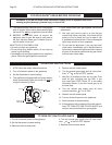
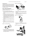
8. Remove the Air Inlet Pipe assembly and Metering
elbow from the gas valve-venturi assembly, Figure
45.
Figure 45 - Air Inlet Pipe Removal
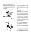
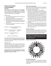
9. Remove the two screws attaching the gas valve-
venturi assembly to the side of the blower and rotate
the valve 90° so the 1/2" threaded connection is
pointing down, Figure 46. Pay close attention to how
the cork gasket is aligned.
Figure 46 - Gas Valve Rotation
10. Reattach the gas valve-venturi assembly to the side
of the blower making sure the gasket is correctly
orientated.
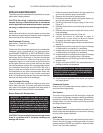
11. Re-install the Air Inlet Pipe assembly and Metering
elbow from the gas valve-venturi assembly, in the
vertical position, Figure 47.
Figure 47 - Air Inlet Pipe Installation
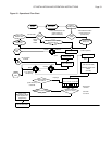
12. Install the gas line as per Figure 48 and follow
the instructions in the GAS PIPING section of this
manual.
Figure 48 - Gas Supply Piping
out
out
out
out
1/2 IN THREADED
CONNECTION
REMOVE SCREWS
AND ROTATE 90°
RE-INSTALL SCREWS
IN NEW LOCATIONS
NEW LOCATIONS
FOR SCREWS