


GT INSTALLATION AND OPERATION INSTRUCTIONS Page 37
This is displayed when the boiler is
expecting the air switch to be closed by a
differential pressure generated when the
combustion blower turns on. It can occur
momentarily during normal operation.
A problem is indicated when ASO is
displayed continuously.
This is displayed when the boiler has
turned the blower off and is expecting
the air switch to be open. It can occur
momentarily during normal operation.
A problem is indicated when ASC is
displayed continuously.
Check for 24 Volts between terminal B1
on Sentry & Ground.
Check for 24 Volts between terminal F1
on Sentry & Ground.
Water Safety Limit trips (Automatic reset)
Located in the supply manifold inside the
boiler cabinet.
ASO
Indicates that the
Air Switch is Open
ASC
Indicates that the
Air Switch is Closed
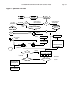
Ignition Sequence
not activated when
burner light is on
(Fan is on and
Fenwal not fl ashing)
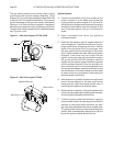
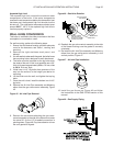
1. Are the vinyl tubes connected between
the air switch and the ports on the inlet
pipe. Negative side of switch connects
to the port on the 1 1/2 in, 38 mm,
ABS elbow.
2. Check for blockage on the intake and
exhaust vents.
3.
If fan is running, air switch may be faulty,
ensure that it’s set for 0.2 in, 5.1 mm WC.
The GT-400 condensate drain switch
must be set at 3 in, 76 mm WC.
4. If fan is not running, check 120V wiring
to blower, if ok remove low voltage
harness from blower, if blower fails to
start, replace blower, if blower does
start problem may be with blower or
Sentry control.
1. Is the fan running. If so check for 24V
between C and D terminals, see wiring
diagrams. If 24V is not present replace
transformer.
2. Check venting termination with
required venting described in manual.
1. If there is 24V, indicates faulty wiring
between BI and W1 on Fenwal, or
faulty Fenwal.
2. If 24V is not present proceed to next
step.
1. If 24V exists here but not at B1,
indicates faulty relay inside Sentry,
contact NTI, replace control.
2. If 24V is not present check for 24V
at transformer.
3. If 24V exists at transformer, check
wiring and safety limits. If 24V not
present at transformer, check wiring
and replace transformer if necessary.
May be caused by an error in the reading
of the water temperature by the Sentry
control. Watch cycle, and ensure the
Sentry is displaying the correct water
temperature and is modulating.
This device protects the boiler from
overheating due to a lack of fl ow passing
through the unit when the burner is on.
FLOW MUST NEVER BE BLOCKED BY
ANY VALVES INCLUDING MIXING OR
ZONE VALVES.
Install unit as described in this manual.
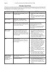
Problem Detected Problem Solution