


GT INSTALLATION AND OPERATION INSTRUCTIONS Page 7
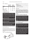
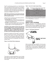
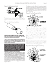
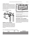
When penetrating an outside wall the air intake and vent
pipes must be constrained as shown in Figure 6. The
openings through which the air intake and vent pipes
pass must be properly sealed to prevent products of
combustion from entering the building.
WARNING: Failure to properly install and seal
the air intake and vent system can result in
excessive levels of carbon monoxide which can
cause severe personal injury or death!
Figure 6 - Wall Penetration Detail
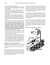
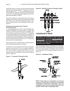
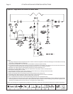
In some cases it may be necessary to attach the air
intake and vent pipes to the outside wall for added rigidity,
Figure 7. If this is the case, special bracket GT-82075
must be ordered for each pipe. Proper clearances must
be maintained.
Figure 7 - Air Intake & Vent Pipe Attachment
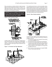
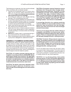
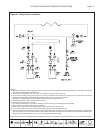
For installations that have to exit the foundation below
grade excavate the site as shown in Figure 8 to a point
below where the pipes exit the building. Maintain the
proper vent clearances as outlined above. Attach the vent
and air intake pipes to the outside of the building using
special bracket 82075. Ensure that the wall penetrations
are properly sealed before backfi lling the site.
Figure 8 - Below Grade Installation
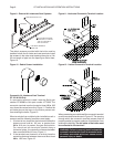
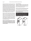
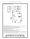
If required, the air intake and vent systems may be run
along an outside wall, Figure 9, providing the following
conditions are met:
1. The maximum length on the outside of the building
is not more than 20 ft, 6.1 m.
2. All normal termination clearances are maintained.
3. The entire vent system external to the building is
insulated using closed cell foamed polyolefi n tubing
having a minimum wall thickness of 1/2 in, 13 mm.
4. The air intake and vent systems are supported
every 24 in, 610 mm.
5. The air intake and vent systems are sloped 1/4 in/ft,
21mm/m back toward the boiler.