3. Combustion & Ventilation Air
For Single Pipe Installation
CARBON MONOXIDE POISONING HAZARD
Failure to provide adequate combustion and
ventilation air could result in death and/or personal
injury.
Use methods described here to provide combustion
and ventilation air.
Furnaces require ventilation openings to provide sufficient air for
proper combustion and ventilation of flue gases. All duct or open-
ings for supplying combustion and ventilation air must comply with
National Fuel Gas Code, NFPA54/ANSI Z223.1, 2002 (or current
edition) and applicable provisions of local building codes.
This furnace can NOT be common vented or connected to any
type B, BW or Lvent or vent connector, nor to any portion of a facto-
ry- built or masonry chimney. Ifthis furnace is replacing a previous-
ly common-vented furnace, it may be necessary to resize the
existing vent and chimney to prevent oversizing problems for the
other remaining appliance(s). See "Venting and Combustion Air
Check"in this section, This furnace MUST be vented to the out-
side.
Air Openings and Connecting Ducts
2,
3.
Total input rating for all non direct vent gas appliances
MUST be considered when determining free area of open-
ings.
Connect ducts or openings directly to outside.
When screens are used to cover openings, they MUST be
no less than 1/4" mesh.
The minimum dimension of rectangular air ducts MUST
NOT be less than 3".
5. When sizing grille or louver, use the free area of opening. If
free area is NOT stamped or marked on grill or louver, as-
sume a 20% free area for wood and 60% for metal.
Confined Space Installation
NOTE: A confined space is defined as an area with less than 50
cubic feet per 1,000 BTUH input rating for all gas appliances
installed in the area.
Requirements
Provide confined space with sufficient air for proper com-
bustion and ventilation of flue gases using horizontal or ver-
tical ducts or openings.
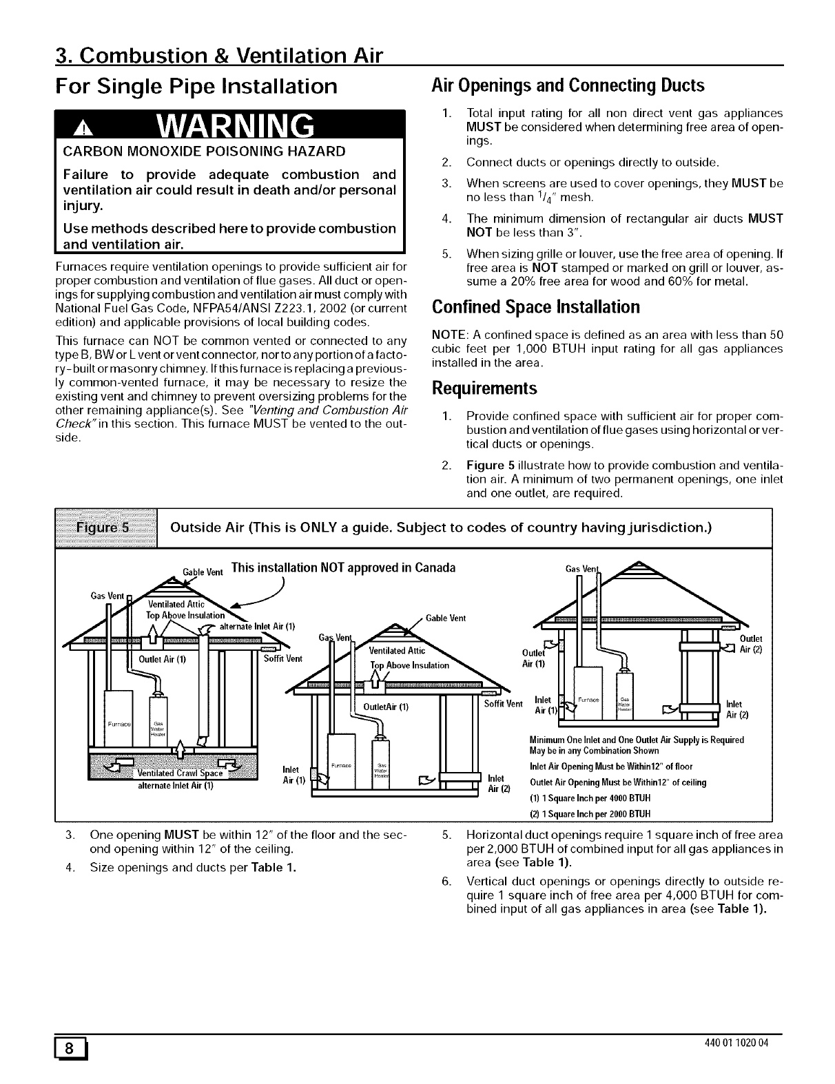
Figure 5 illustrate how to provide combustion and ventila-
tion air. A minimum of two permanent openings, one inlet
and one outlet, are required.
Outside Air (This is ONLY a guide. Subject to codes of country having jurisdiction.)
Gas Vent
CableVent This installation NOT approved in Canada GasVen_.
.J
x. c,,en .... ,dNI a___aOut,et
Outlet Air (1) Soffit Vent /
') I I _ ;_.-u,atio.'>_ .ir(1)I JL__.q3 II II
II 11I II II
r-q I I ]- OutletAir'l' _] I SoffitVent In.let _4........I I_;:;:,1 ___.L_U, tnlet
I I A _ _ -- _ II I MinimumOnelnletandOneOutletAirSupplyisRequired
I I II I May bein any Combination Shown
Inlet _ ,r_o, I _"_1 I I I Inlet Air Opening Must be Within12" of floor
alternate lnlet Air (1) AIr(l) _ Iq [_:_"r_r _ilrei2) OutletAirOpeningMustbeWithinl2"ofceiling
(1)1SquareInchper4000BTUH
(2)1SquareInchper2000B]-UH
3. One opening MUST be within 12" of the floor and the sec-
ond opening within 12" of the ceiling.
4. Size openings and ducts per Table 1.
5. Horizontal duct openings require I square inch of free area
per 2,000 BTUH of combined input for all gas appliances in
area (see Table 1).
6. Vertical duct openings or openings directly to outside re-
quire 1 square inch of free area per 4,000 BTUH for com-
bined input of all gas appliances in area (see Table 1).
E_ 44001102004


