


1,
Install all couplings, nipples and elbows using proper proce-
dures for Joining Pipe and Fittings and maintain spacing
between vent and combustion air piping as indicated in
Figure 20 through Figure 28.
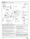
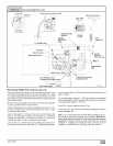
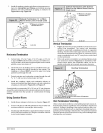
MIN.
_18"Minimumfor coldclimates
(substained below0° F)
MIN.
GRADELEVEL 25-00-05F
ON
SNOW LEVEL
Horizontal Termination
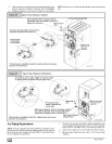
1,
Cut two holes. 21/2" for 2" pipe, 3" for 21/2" pipe, or 31/2" for
3" pipe. Do NOT make the holes oversized, or it will be nec-
essary to add a sheet metal or plywood plate on the outside
with the correct size hole in it.
2,
Check hole sizes by making sure it is smaller than the cou-
plings or elbows that will be installed on the outside. The
couplings or elbows MUST prevent the pipe from being
pushed back through the wall.
3. Extend vent pipe and combustion air pipe through the wall
3/4" to 1" and seal area between pipe and wall.
4. Install the couplings, nipple and termination elbows as
shown and maintain spacing between vent and combustion
air piping as indicated in Figure 20 and Figure 21.
Ametal shield isrecommended 18" x 18" min. or 18" min. diameter
around the vent termination atthe exterior wall to protect the house
exterior materials from flue product or condensation (freezing)
damage.
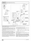
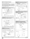
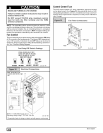
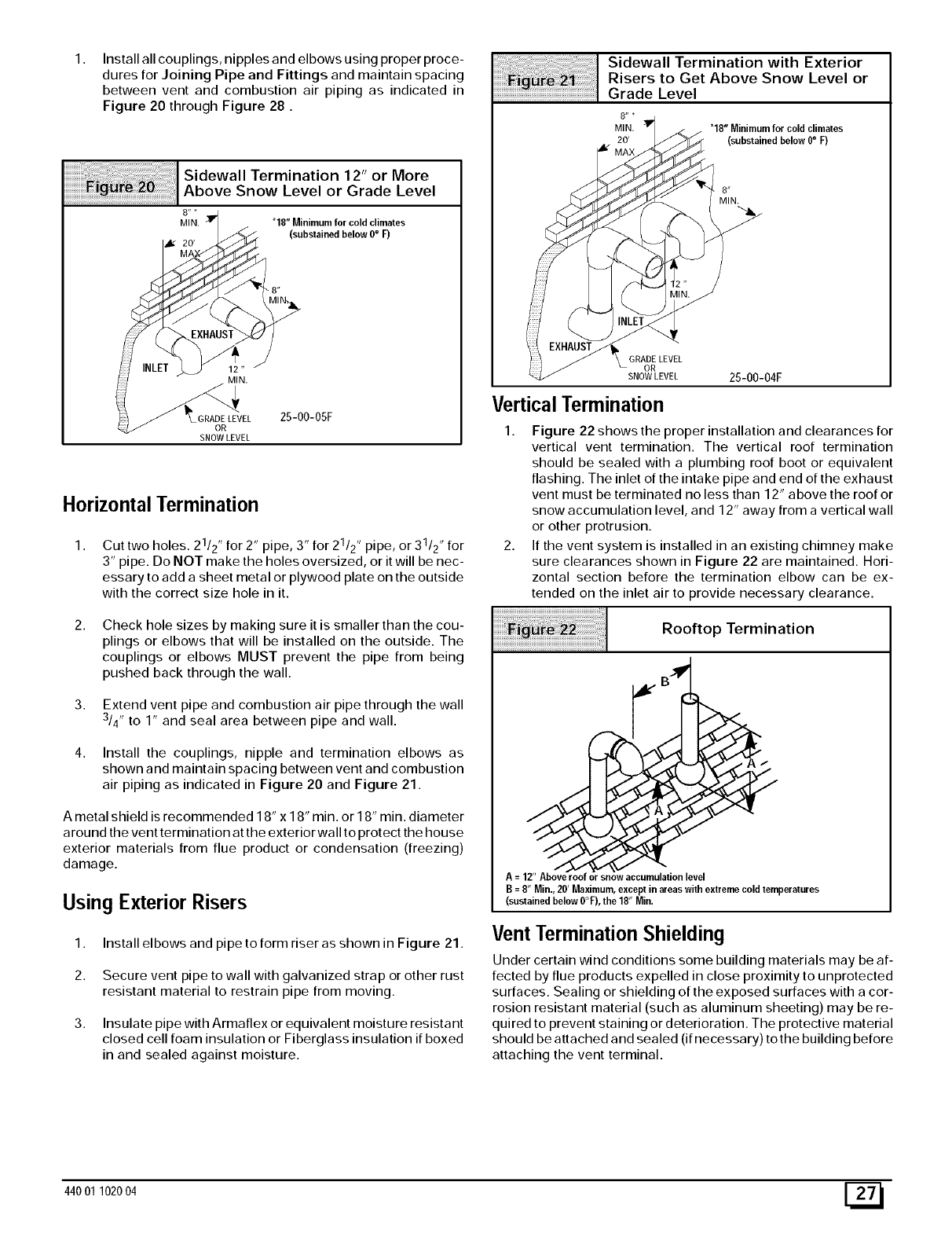
Using Exterior Risers
1,
2.
3,
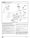
Install elbows and pipe to form riser as shown in Figure 21.
Secure vent pipe to wall with galvanized strap or other rust
resistant material to restrain pipe from moving.
Insulate pipe with Armaflex or equivalent moisture resistant
closed cell foam insulation or Fiberglass insulation if boxed
in and sealed against moisture.
........................................................................._!i i I Risers t° Get Ab°ve sn°w Level°rGradesidewallLeveITerminati°nwith Exterior
8" *
MIN. _ "18" Minimum for cold climates
20' (substained below 0° F)
JW MAX
8"
MIN.
• GRADE LEVEL
OR
SNOW LEVEL 25-00-04F
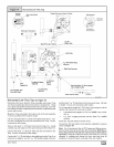
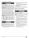
Vertical Termination
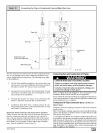
1. Figure 22 shows the proper installation and clearances for
vertical vent termination. The vertical roof termination
should be sealed with a plumbing roof boot or equivalent
flashing. The inlet of the intake pipe and end of the exhaust
vent must be terminated no less than 12" above the roof or
snow accumulation level, and 12" away from a vertical wall
or other protrusion.
2. If the vent system is installed in an existing chimney make
sure clearances shown in Figure 22 are maintained. Hori-
zontal section before the termination elbow can be ex-
tended on the inlet air to provide necessary clearance.
Rooftop Termination
A=12"Aboverooforsnowaccumulationlevel
B=8"Min.,20'Maximum,exceptinareaswithextremecoldtemperatures
(sustainedbelow0°%the18"Min.
Vent Termination Shielding
Under certain wind conditions some building materials may be af-
fected by flue products expelled in close proximity to unprotected
surfaces. Sealing or shielding of the exposed surfaces with a cor-
rosion resistant material (such as aluminum sheeting) may be re-
quired to prevent staining or deterioration. The protective material
should be attached and sealed (if necessary) to the building before
attaching the vent terminal.
44001 102004 [_