


bustionorthefurnacecanuseairfrominsidethestructureforcom-
bustion.TheINLETairpipeisoptional.Ifcombustionaircomes
frominsidethestructure,adequatemakeupairMUSTbeprovided
tocompensateforoxygenburned.SeeConfined Space Installa-
tion in the Combustion and Ventilation Air chapter. If combus-
tion air is drawn from outside the structure, it MUST be taken from
the same atmospheric pressure zone as the vent pipe.
Contaminated Combustion Air
Installations in certain areas or types of structures will increase the
exposure to chemicals or halogens that may harm the furnace.
The following areas or types of structures may contain or have ex-
posure to the substances listed below. The installation must be
evaluated carefully as it may be necessary to provide outside air
for combustion.
• Commercial buildings.
• Buildings with indoor pools.
• Furnaces installed in laundry rooms.
• Furnaces installed in hobby or craft rooms.
• Furnaces installed near chemical storage areas.
• Permanent wave solutions for hair.
• Chlorinated waxes and cleaners.
• Chlorine based swimming pool chemicals.
• Water softening chemicals.
• De-icing salts or chemicals.
• Carbon tetrachloride.
• Halogen type refrigerants.
• Cleaning solvents (such as perchloroethylene).
• Printing inks, paint removers, varnishes, etc.
• Hydrochloric acid.
• Sulfuric Acid.
• Solvent cements and glues.
• Antistatic fabric softeners for clothes dryers.
• Masonry acid washing materials.
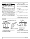
Vent and Combustion Air Piping Guidelines
This furnace is approved for venting with Schedule 40 PVC,
CPVC, ABS, Cellular Core pipe fittings and SDR-26 PVC.
NOTE: All PVC, CPVC, ABS, and Cellular Core pipe fittings, sol-
vent cement, primers and procedures MUST conform to American
National Standard Institute and American Society for Testing and
Materials (ANSI/ASTM) standards.
• Pipe and Fittings - ASTM D1785, D2241, D2466, D2661,
D2665, F-891, F-628
• PVCPrimerandSolventCement- ASTM D2564
• Procedure for Cementing Joints - Ref ASTM D2855
NOTE: All vent piping MUST be installed in compliance with local
codes or ordinances, these instructions, good trade practices, and
codes of country having jurisdiction.
1. Determine the best routing and termination for the vent pipe
and air inlet pipe by referring to all of the instructions and
guidelines in this Section.
2. Determine the size required for the vent pipe and air inlet
pipe.
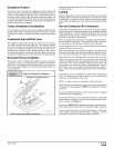
3. Loosely assemble all venting parts without adhesive (pipe
joint cement) for correct fit before final assembly.
44001102004
4. Use of vertical piping is preferred because there will be
some moisture in the flue gases that may condense as it
leaves the vent pipe (See 5peciallnstruction ForHorizontal
Vents).
5. The vertical vent pipe MUST be supported so that no weight
is allowed to rest on the combustion blower.
6. Exhaust vent piping or air inlet piping diameter MUST NOT
be reduced.
7. All exhaust vent piping from the furnace to termination
MUST slope upwards. A minimum of 1/4" per foot of run is
required to properly return condensate to the furnace drain
system.
8. Use DWV type long radius elbows whenever possible, as
they provide for the minimum slope on horizontal runs and
they provide less resistance in the vent system. If DWV el-
bows cannot be used, use two, 45 ° elbows when possible.
On horizontal runs the elbows can be slightly misaligned to
provide the correct slope.
9. All horizontal pipe runs MUST be supported at least every
five feet with galvanized strap or other rust resistant materi-
al. NO sags or dips are permitted.
10. All vertical pipe runs MUST be supported every six feet
where accessible.
11.
12.
The minimum pipe run length is 2'.
The piping can be run in the same chase or adjacent to sup-
ply or vent pipe for water supply or waste plumbing. It can
also be run in the same chase with a vent from another 90+
furnace.
NOTE: In NO case can the piping be run in a chase where
temperatures can exceed 140 ° F. or where radiated heat
from adjacent surfaces would exceed 140 ° F.
13. The vent outlet MUST be installed to terminate in the same
atmospheric pressure zone as the combustion air inlet.
14. The vent system can be installed in an existing unused
chimney provided that:
• Both the exhaust vent and air intake run the length of the
chimney.
• No other gas fired appliance or fireplace (solid fuel) is
vented into the chimney.
• The top of the chimney MUST be sealed flush or crowned
up to seal against rain or melting snow so ONLY the piping
protrudes.
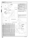
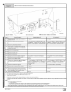
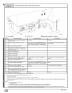
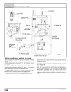
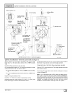
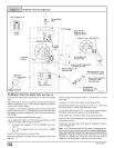
• Thetermination clearances shown in Figure 7 & Figure 8
are maintained.
15. Furnace applications with vertical vents requiring vent di-
ameter increaser fittings must have increaser fittings
installed in vertical portion of the vent. Condensate will be
trapped in the vent if the vent diameter is increased prior to
having an elbow turned upward. This could cause nuisance
tripping of the pressure switch.
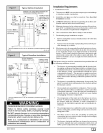
Piping InsulationGuidelines
NOTE: Use closed cell, neoprene insulation or equivalent. If Fiber-
glass or equivalent insulation is used it must have a vapor barrier.
Use R values of 7 up to 10', R- 11 ifexposure exceeds 10'. If Fiber-
glass insulation is used, exterior to the structure, the pipe MUST
be boxed in and sealed against moisture.
1. When the vent or combustion air pipe height above the roof
exceeds 30", or if an exterior vertical riser is used on a hori-
zontal vent to get above snow levels, the exterior portion
MUST be insulated.
When combustion air inlet piping is installed above a sus-
pended ceiling, the pipe MUST be insulated with moisture
resistant insulation such as Armaflex or other equivalent
type of insulation.
E!9