


5. Gas Supply and Piping
CARBON MONOXIDE POISONING, FIRE AND
EXPLOSION HAZARD.
Failure to follow these instructions could result in
death, personal injury and/or property damage.
Models designated for Natural Gas are to be used
with Natural Gas ONLY, unless properly converted to
use with LP gas.
NOTE: The rating plate is stamped with the model number, gas
type and gas input rating. In addition, models manufactured for
sale in Canada have orifice size information stamped on the rating
plate.
Alternate BTUH Input Ratings (USA Only)
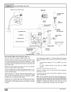
The input rating of these furnaces can be changed from the stan-
dard input rating to the alternate input rating shown in Table 5, by
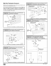
changing the main burner orifices. NOTE: The input rating ot
80,000 BTUH models cannot be changed from the standard input.
Changing of burner orifices MUST be done by a qualified service
technician. See section on changing orifices or following page.
IAIternate Input Ratings, USA ONLY.
BTUH BTUH Natural LP
Standard Alternate Gas Gas
Rating Rating Orifice Orifice
50,000 40,000 #44 #55
75,000 60,000 #44 #55
100,000 80,000 #44 #55
125,000 100,000 #44 #55
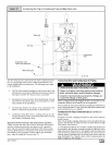
Supply Pressure
FIRE HAZARD
Failure to properly set input pressure could result in
death, personal injury and/or property damage.
Do NOT set input rating above that shown on rating
plate.
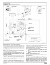
1. Supplypressurecanbecheckedusingthel/8 " NPTporton
the supply side of the gas valve.
2. Gas input to burners MUST NOT exceed the rated input
shown on rating plate.
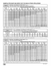
3. Do NOT allow minimum gas supply pressure to vary down-
ward. Doing so will decrease input to furnace. Refer to
Table 6 for normal gas supply and manifold pressures.
Gas SupplyPressure
Gas supply pressure should be within minimum and maximum val-
ues listed on rating plate. Pressures are usually set by gas suppli-
ers.
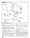
Manifold Gas Pressure Adjustment
NOTE: Make adjustment to manifold pressure with burners oper-
ating.
ELECTRICAL SHOCK HAZARD.
Failure to do so could result in death, personal
injury and/or property damage.
Turn OFF power to furnace before changing speed
taps.
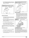
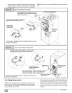
1. Remove the burner compartment door.
2. With gas OFF, connect manometer to tapped opening on
gas valve. Use manometer with a 0 to 15" water column
range.
3. Turn gas ON. Operate the furnace by using ajumper wire on
the R to W thermostat connections on the fan board.
4. Remove manifold pressure adjustment screw cover on fur-
nace gas control valve. Turn adjusting screw counterclock-
wise to decrease manifold pressure and clockwise to
increase pressure.
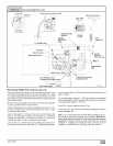
NOTE: Adjustment screw cover MUST be replaced on gas control
valve before reading manifold pressure and operating furnace.
5. Set manifold pressure to value shown in Table 6, Table 7,
Table 8 or Table 9.
6. When the manifold pressure is properly set, replace the ad-
justment screw cover on the gas control valve.
7. Remove jumper wire from thermostat connection on fan
board. Remove manometer connection from manifold
pressure tap, and replace plug in manifold.
8. Check for leaks at plug.
9. Replace the burner compartment door.
44001 102004 [_