


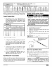
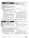
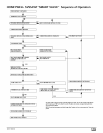
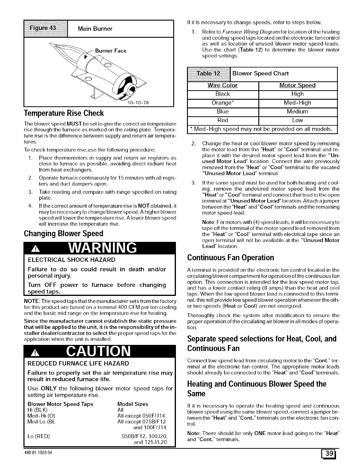
Main Burner
Face
10-10-78
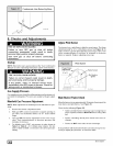
Temperature Rise Check
The blower speed MUST be set to give the correct air temperature
rise through the furnace as marked on the rating plate. Tempera-
ture rise is the difference between supply and return air tempera-
tures.
To check temperature rise,use the following procedure:
1. Place thermometers in supply and return air registers as
close to furnace as possible, avoiding direct radiant heat
from heat exchangers.
2. Operate furnace continuously for 15 minutes with all regis-
ters and duct dampers open.
3. Take reading and compare with range specified on rating
plate.
4. If the correct amount of temperature rise is NOT obtained, it
may be necessary to change blower speed. A higher blower
speed will lower the temperature rise. A lower blower speed
will increase the temperature rise.
Changing Blower Speed
ELECTRICAL SHOCK HAZARD
Failure to do so could result in death and/or
personal injury.
Turn OFF power to furnace before changing
speed taps.
NOTE: The speed taps that the manufacturer sets from the factory
for this product are based on a nominal 400 CFM per ton cooling
and the basic mid range on the temperature rise for heating.
Since the manufacturer cannot establish the static pressure
that will be applied to the unit, it is the responsibility of the in-
staller dealer/contractor to select the proper speed taps for the
application when the unit is installed.
REDUCED FURNACE LIFE HAZARD
Failure to properly set the air temperature rise may
result in reduced furnace life.
Use ONLY the following blower motor speed taps for
setting air temperature rise.
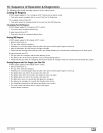
Blower Motor Speed Taps Model Sizes
Hi (BLK) All
Med-Hi (O) All except 050F/J14
Med Lo (BL All except 075B/F12
and 100F/J14
Lo (RED) 050B/F12,100J20,
and 125J/L20
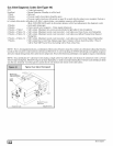
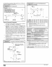
If it is necessary to change speeds, refer to steps below.
Refer to Furnace WMng Diagramfor location of the heating
and cooling speed taps located on the electronic fan control
as well as location of unused blower motor speed leads.
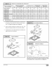
Use the chart (Table 12) to determine the blower motor
speed settings.
Blower Speed Chart
Wire Color
Black
Orange*
Blue
Red
Motor Speed
High
Med-High
Medium
Low
* Med-High speed may not be provided on all models.
Change the heat or cool blower motor speed by removing
the motor lead from the "Heat" or "Cool" terminal and re-
place it with the desired motor speed lead from the "Un-
used Motor Lead" location. Connect the wire previously
removed from the "Heat" or "coor' terminal to the vacated
"Unused Motor Lead" terminal.
If the same speed must be used for both heating and cool-
ing, remove the undesired motor speed lead from the
"Heat" or "Cool" terminal and connect that lead to the open
terminal at "Unused Motor Lead" location. Attach ajumper
between the "Heat" and "Cool" terminals and the remaining
motor speed lead.
Note: For motors with (4) speed leads, it will be necessaryto
tape off the terminal of the motor speed lead removed from
the "Heat" or "coor' terminal with electrical tape since an
open terminal will not be available at the "Unused Motor
Lead" location.
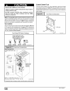
Continuous Fan Operation
A terminal is provided on the electronic fan control located in the
circulating blower compartment for operation of the continuous fan
option. This connection is intended for the low speed motor tap,
and has a lower contact rating (8 amps) than the heat and cool
taps. When the low speed blower lead is connected to this termi-
nal, this will provide low speed blower operation whenever the oth-
er two speeds (Heat or Cool) are not energized.
Thoroughly check the system after modification to ensure the
proper operation of the circulating air blower in all modes of opera-
tion.
Separate speed selections for Heat, Cool, and
Continuous Fan
Connect low speed lead from circulating motor to the "Cont." ter-
minal at the electronic fan control. The appropriate motor leads
should already be connected to the "Heat" and "coor' terminals.
Heating andContinuous BlowerSpeed the
Same
If it is necessary to operate the heating speed and continuous
blower speed using the same blower speed, connect ajumper be-
tween the "Heat" and "Cont." terminals on the electronic fan con-
trol.
Note: There should be only ONE motor lead going to the "Heat"
and "Cont." terminals.
44001 102004 E_