


3. Insulate combustion air inlet piping when run in warm, hu-
mid spaces such as basements.
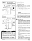
Sizing Combustion Air and Vent Pipe
Consult Table 3 or Table 4 to select the proper diameter exhaust
and combustion air piping. Exhaust and combustion air piping is
sized for each furnace Btuh size based on total lineal vent length
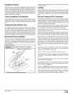
(on inlet oroutlet side), and number of 90 ° elbows required. Two
45 ° elbows can be substituted for one 90 ° elbow. The elbow or el-
bows used for vent termination outside the structure ARE counted,
including elbows needed to bring termination above expected
snow levels. The elbow inside the furnace on the *9MPD IS NOT
included in the count.
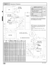
Pipe Diameter Table
N9MP1 & *9MPD Models
50,000, 75,000 & 80,000 Btuh Furnaces
40' & (5) 90° elbows with 2" PVC pipe or
70' & (5) 90° elbows with 3" PVC pipe
100,000 Btuh Furnace
40' & (5) 90° elbows with 3" PVC pipe or
70' & (5) 90° elbows with 3" PVC pipe &
Long Vent Kit (See Tech. Manual)
125,000 Btuh Furnace
40' & (5) 90° elbows with 3" PVC pipe
Elbows are DWV Long Radius Type for 2" and 3" vents.
If more than five elbows are required, reduce the length of
both the inlet and exhaust pipes 5' for each additional elbow
used.
NOTE: It is allowable to use larger diameter pipe and fitting than
shown in the tables but not smaller diameters than shown.
Pipe Diameter Table
N9MP2 Models
50,000 & 80,000 Btuh Furnaces
40' & (5) 90° elbows with 2" PVC pipe or
70' & (5) 90° elbows with 3" PVC pipe
75,000 Btuh Furnaces
25' & (3) 90° elbows with 2" PVC pipe or
40' & (5) 90° elbows with 2" PVC pipe &
Long Vent Kit (See Tech. Manual) or
70' & (5) 90° elbows with 3" PVC pipe
100,000 Btuh Furnace
40' & (5) 90° elbows with 3" PVC pipe or
70' & (5) 90° elbows with 3" PVC pipe &
Long Vent Kit (See Tech. Manual)
125,000 Btuh Furnace
40' & (5) 90° elbows with 3" PVC pipe
Elbows are DWV Long Radius Type for 2" and 3" vents.
If more than five elbows are required, reduce the length of
both the inlet and exhaust pipes 5' for each additional elbow
used.
For "Concentric Termination Kit" Venting table, see
"Section 11" in this manual.
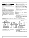
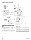
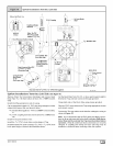
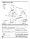
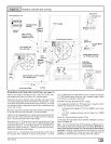
Vent Termination Clearances
CARBON MONOXIDE POISONING, FIRE AND
EXPLOSION HAZARD.
Failure to properly vent this furnace could result in
death, personal injury and/or property damage.
Inlet and outlet pipes may NOT be vented directly
above each other.
1. Determine termination locations based on clearances spe-
cified infollowing steps and as shown in Figure 7, Figure 8,
Figure 20, through Figure 28.
For "Concentric Termination Kit"clearances, see Figure 46,
Figure 47, Figure 48, Figure 49 and Figure 50 in "Section 10"
in this manual.
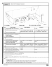
2. For Single Pipe Installation, models N9MP1 or *9MPD, refer
to Figure 8 for vent termination clearances.
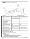
3. For Direct Vent Installation, models N9MP2 or*9MPD, refer
to Figure 7 for vent termination clearances.
[_ 44001102004