


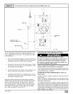
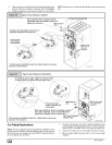
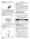
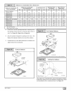
NOTE:RefertoFigure30orFigure31forthegenerallayoutat
thefurnace.TheruleslistedapplytonaturalandLPgaspipe
installations.
NOTE:OntheDualCertifiedorDirectVentmodels,installthegas
pipegrommettothefurnacesidepanelwiththegaspipeentry.If
needed,removethe2"holeplugandrelocatetotheopenholein
thefurnacesidepanel.
FIRE OR EXPLOSION HAZARD
Failure to properly install metal gas connector
could result in death, bodily injury and/or property
damage.
A flexible corrugated metal gas connector must be
properly installed, shall not extend through the side
of the furnace,and shall not be used inside the
furnace.
Black iron pipe shall be installed at the furnace gas
control valve and extend a minimum of 2" outside
furnace casing.
4. Use black iron or steel pipe and fittings or other pipe ap-
proved by local code.
NOTE: The use of copper tubing for gas piping is NOT approved
by the state of Massachusetts.
5. Use ground joint unions and install a drip leg no less than 3"
long to trap dirt and moisture before it can enter gas valve.
6. Use two pipe wrenches when making connections to pre-
vent gas valve from turning.
7. Install a manual shut-off valve external to furnace casing
and tighten all joints securely.
Additional LP Connection Requirements
1. Have a licensed LP gas dealer make all connections at stor-
age tank and check all connections from tank to furnace.
2. If copper tubing is used, it MUST comply with limitation set in
National Fuel Gas Code or CGA codes.
3. Two-stage regulation of LP gas is recommended.
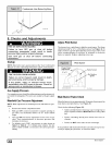
Final Check
3.
4.
5.
The furnace and the gas valve must be disconnected from the
gas supply piping system during any pressure testing of that
system at test pressures in excess of 1/2" PSIG. Close the
manual shut-off valve before testing at such pressures.
When installation is complete, test all pipe connections for
1 ,
leaks with the gas pressure less than /2' PSIG to the gas
valve.
Apply a commercial soap solution to all joints to test for
leaks. Correct any leaks indicated by bubbles.
Correct even the smallest leak at once.
Check for leaks at gas valve and orifice connections to the
burner manifold along with the pilot tube connections to the
valve and pilot assembly while the furnace is operating.
6. Electrical Wiring
ELECTRICALSHOCK HAZARD.
Failure to do so could result in death, personal
injury and/or property damage.
Turn OFF electrical power at fuse box or service
panel before making any electrical connections
and ensure a proper ground connection is made
before connecting line voltage.
Power SupplyWiring
The furnace MUST be electrically wired and grounded in accor-
dance with local codes, or in the absence of local codes with the
latest edition of The National Electric Code, ANSI N FPA 70 and/or
The Canadian Electric Code CSA C22.1.
The power supply to the furnace connections must be between
104 VAC and 127 VAC during furnace operation for acceptable
performance.
Field wiring connections must be made inside the furnace connec-
tion box. A suitable strain relief should be used at the point the
wires exit the furnace casing.
I Copper conductors shall be used. Line voltage wires should
conform to temperature limitation of 63 ° F (35 ° C) rise and be sized
for the unit maximum amps stated on the rating plate. Add the full
load amps for potential field-installed accessories such as elec-
tronic air cleaners and humidifiers that would receive power from
the furnace control. The furnace control is rated for a maximum of
0.8 amps combined for EAC and Hum. Consult N EC or local codes
for proper wire and circuit sizing.
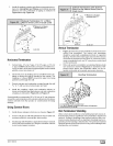
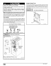
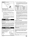
J- Box Relocation
The j-box is installed on left side of casing. An alternate j-box
location on right side can be used.
1. Remove bag containing two hole plugs and two self tapping
screws from loose parts bag in blower compartment.
2. Remove two screws holding j-box to casing.
3. Move large hole plug from right to left j-box location.
4. Move j-box to alternate location and attach using two self
tapping screws from bag.
5. Apply two hole plugs from bag at left j-box location.
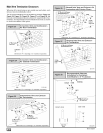
Thermostat
Thermostat location has an important effect on the operation of the
unit. Follow instructions included with thermostat for correct
mounting and wiring.
Low voltage connections to furnace must be made on terminal
board to fan control.
Set thermostat heat anticipator in accordance with the Technical
Support Manual.
Optional Equipment
All wiring from furnace to optional equipment MUST conform to lo-
cal codes or, in the absence of local codes with the latest edition of
The National Electric Code, ANSI NFPA 70 and/or The Canadian
Electric Code CSA C22.1. Install wiring in accordance with
manufacturer's instructions. The wiring MUST have a minimum
temperature rating of 105 ° C.
Humidifier/Electronic Air Cleaner
The furnace is wired for humidifier and/or electronic air cleaner
connection.
440O1102004 E_