


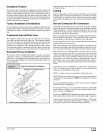
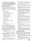
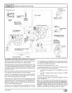
CondensateDrainTrap
This furnace removes both sensible and latent heat from the prod-
ucts of combustion. Removal of the latent heat results in con-
densation of the water vapor. The condensate is removed from the
furnace through the drains in the plastic transition and the vent fit-
ting. The drains connect to the externally mounted condensate
drain trap on the left or right side of the furnace.
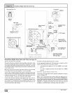
The startup of a new furnace will involve a cycle or two of the fur-
nace to properly prime the condensate trap with water. Until the
trap is fully primed, some condensate will be pulled into the com-
bustion blower. The furnace may cycle on the pressure switch con-
nected to the plastic transition box due to condensate buildup.
After the trap is primed, the condensate will start draining from the
furnace. The combustion blower will clear out any remaining con-
densate in the blower housing through the vent fitting downstream
of the blower. Note that the condensate trap can also be primed by
pouring water into the 1/2" drain hose. Remove the1/2 " ID drain
hose from either the gutter or the white PVC Tee Trap. Using a fun-
nel pour eight (8) ounces of water into 112" ID drain hose.Water will
flow through the drain hose and into the condensate drain trap.
This will prime both the vent and the transition sides of the trap. Re-
connect the 1/2, ID drain hose to the original component, either the
gutter or the PVC Tee Trap.
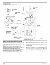
The condensate drain trap supplied with the furnace MUST be
used. The drain connection on the condensate drain trap is sized
for 3/4" PVC or CPVC pipe, however alternate 1/2" CPVC (nominal
5/8" O.D.) or vinyl tubing with a minimum inner diameter (I.D.) of
5/8" may also be used, as allowed by local codes. Alternate drain
pipes and hoses may be used as allowed by local codes.
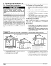
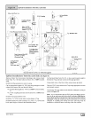
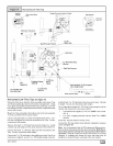
The drain line must maintain a I/4" per foot downward slope toward
the drain. 114"per foot is recommended. Installation of an overflow
line is recommended when the 114" per foot slope to the conden-
sate drain cannot be maintained. See Figure 18 for proper routing
and installation of the overflow.
DO NOT trap the drain line in any other location than at the con-
densate drain trap supplied with the furnace.
FROZEN AND BURST WATER PIPE HAZARD
Failure to do so could result in burst water pipes,
serious property damage and/or personal injury.
If a condensate pump is installed, a plugged
condensate drain or a failed pump may cause the
furnace to shut down. Do not leave the home
unattended during freezing weather without turning
off water supply and draining water pipes or
otherwise protecting against the risk of frozen pipes.
If possible DO NOT route the drain line where it may freeze. The
drain line must terminate at an inside drain to prevent freezing of
the condensate and possible property damage.
1. A condensate sump pump MUST be used if required by lo-
cal codes, or if no indoor floor drain is available. The con-
densate pump must be approved for use with acidic
condensate.
2. A plugged condensate drain line or a failed condensate
pump will allow condensate to spill. If the furnace is installed
where a condensate spill could cause damage, it is recom-
mended that an auxiliary safety switch be installed to pre-
vent operation of the equipment in the event of pump failure
or plugged drain line. If used, an auxiliary safety switch
should be installed in the R circuit (low voltage) ONLY.
3. If the auxiliary switch in the condensate pump is used, the
furnace may shut down dueto a blocked condensate line or
failed pump. To prevent frozen water pipes see the "Frozen
Water Pipe Hazard" section on Page 4 of this manual.
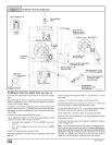
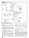
Condensate Drain Trap Freeze Protection
Special precautions MUST be made if installing furnace in an area
which may drop below freezing. This can cause improper opera-
tion or damage to the equipment. If the the furnace environment
has the potential of freezing, the drain trap and drain line must be
protected. Use 3 to 6 watt per foot at 115 volt, 40 ° Fself-regulating
shielded and waterproof heat tape. Wrap the drain trap and drain
line with the heat tape and secure with the ties. Follow the heat
tape manufacturer's recommendations.
44001 102004 E_I