


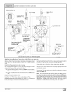

Horizontal Left-Side Vent
Alternate Orienation
Field
Supplied Tee_
TeeTrapWhite PVC
(loosepartsbag)
DrainTubeBlack, /8 IDCorrugated
Cutatstraight section
I
Leav_ Cut Here
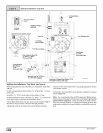
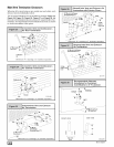
Single Pressure Switch Detail
Level or Sloped towards Tee
Dual Pressure Switch
3/16"ID Ru/bherTube
ReliefTube /
/
U
SpliceConnector
ReliefTubeExtension
Yelloworblack
VentDrain
&Clamps
1/2" IDDrain Elbow
_DrainHose& Splice
Connector
(Cut-to-fit)
,5/8" ID
Corrugated
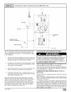
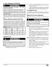
WARNING
MoveCaps to
topoftrap
25-24-48
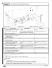
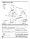
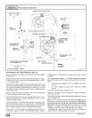
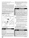
Horizontal Left-Side Vent (SeeFigure 15)
Remove the Drain Tee from the Vent Drain if installed (_9MPD
models only)
Rotate the inducer 180 ° for a side vent after loosening the 4 induc-
er attachment screws. Reinstall and retighten the inducer screws
to 20" pounds torque.
Disconnect the hoses from the Trap assembly, and remove Trap
and Trap mounting bracket from the blower compartment. Using
cover plate and gasket provided in the loose parts bag, cover the
hole from the burner compartment to the blower compartment and
secure with screws.
Mount the Trap externally to the bottom side of the unit using the
2 screws provided in the location shown.
Cut the corrugated tube as shown in the illustration above. Con-
nect the corrugated hose from the transition to the Trap. Secure
connections with clamps.
Connect the black 1/2" ID Drain Tube from the Vent Drain to the
Trap. If an extension is required, use the black 1/2" OD flexibletub-
ing connector and the black 1/2" ID Drain Tube in the loose parts
bag. Cut tube to length. Secure connections with clamps.
Connect the 3/16" ID relief tube to the middle port on the Trap. If an
extension is required, use the 3116"0D flexible tubing connector
and the black 3/16" ID relief tube in the loose parts bag. Cut tube
to length.
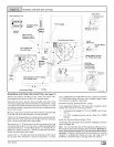
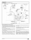
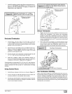
Cut an appropriate length of 2" PVC pipe, fittings and extension
pipe long enough to exit the cabinet and connect the vent drain to
either:
• A standard field supplied 2" PVC tee (N9MP1 and 2 mod-
els), or
• A 2" PVC coupling fastened onto the Drain Tee (*9MPD
models)
Install Tee Trap into bottom section of Tee.
Important: The pipe to the Tee Trap must be level or sloping to-
wards the Tee Trap
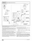
Connect the Tee trap and the main drain line exiting the casing as
shown in Figure 18.
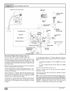
Note: It is recommended that all PVC piping and fitting connec-
tions be fit up and inspected before final cementing. Both the ex-
ternal Trap and the external Tee Trap must be primed before
operation• Verify all condensate drain connections are securely
clamped. A coupling and clamps (in loose part bag) may be
installed as shown for future servicing of the vent system.
A coupling and clamps (in loose part bag) may be installed as
shown for future servicing of the vent system.
[_ 44001102004