


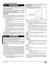
REDUCED FURNACELIFE HAZARD
Failure to follow caution instructions may result in
reduced furnace life.
Do NOT exceed 115V/0.8 amp. maximum current
load for both the EAC terminal and the HUM
terminal combined.
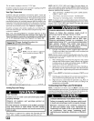
NOTE: The humidifier will be powered when the furnace is fired
and the circulating air blower comes on. The electronic air cleaner
will be powered anytime the air circulating blower is energized.
However, the electronic air cleaner is NOT energized during con-
tinuous fan operation controlled by the electronic fan control.
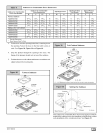
Fan Control
The fan control is preset at the factory with a fixed blower ON delay
of 30 seconds in the heating mode. The blower OFF timing is pre-
set at 140 seconds. If desired, the fan OFF delay can be reset to
obtain the longest delay times while still maintaining comfort lev-
els. See "Furnace Wiring Diagram".
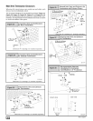
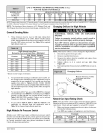
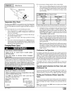
Fan Delay DIP Switch Settings
12
60SEC 100SEC
COOL ON DELAY: 5 SEC,
COOL OFF DELAY: 90 SEC.
HEAT ON DELAY: 30 SEC.
HEAT OFF DELAY
12 12 12
140SE0 180SE0 25-23-47
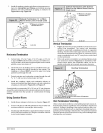
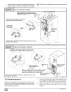
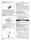
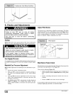
Electrical Connections
......NoTEIJunctionBoxcanbe
mountedtoeithertheleftorright i/" F_/_..._
side FF
z w ,_ #
Gr_nd
/ ..._ J_,'_ _- Models rl ay
_ i_ p r%Vs%lur°_ 2
T .... _) _ -__ switches
i _'°rWiVn°al_laBg°eard(_ /_ _
NOTE 115 VAC/6OHz/single-phase _ _
Operating voltage range*: 127 max, 104 rain. 25-23-42
Permissible limits of voltage at which unit will operate satisfactorily
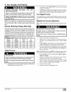
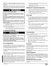
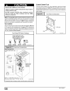
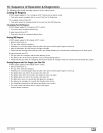
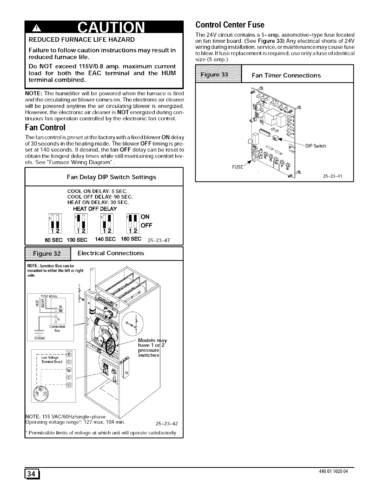
Control Center Fuse
The 24V circuit contains a 5-amp, automotive-type fuse located
on fan timer board. (See Figure 33) Any electrical shorts of 24V
wiring during installation, service, or maintenance may cause fuse
to blow. If fuse replacement is required, use only a fuse of identical
size (5 amp.)
Fan Timer Connections
FUSE/'_r
25-23-41
[_ 44001102004