


DownflowLeftSide Vent and Trap
Yellow or black Plastic Cap
VentDrain
& Clamps
Coupling&Clamps >_
(Optional)_ I._
]|mm|l
Either: The PrO
DrainTeeora field
supplied 2"PVCTee
TeeTrapWhttePVC___ _
(loosepartsbag)-__ Hose
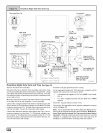
Single Pressure Switch Detail
o Drain
E,how!l
WARNING _._
_1 M°veCap s
_1 totopof U
trap _/
DrainTubeBlack,s/8"IDCorrugated /
Cut at straight section /
Lea_
2" PVCCoupling
Dual Pressure Switch
©
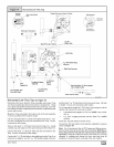
SIDE VIEW
/,,_ Rotate downward
NOTE_. Bw]t-in channel will
be angled 5° to 10° also.
3/16"ID
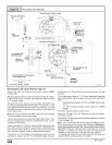
OnSome Models
ONLY
INLET _) 4=
Connector,
3/16" OD (loose parts hag)
ReliefTube,
- Extension Black,
3/16"IDCut tofit
(loosepartsbag)
1_ TrapConnection
Preassemble &
insert into furnace
25-24-45
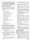
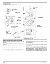
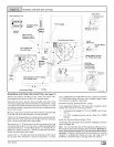
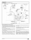
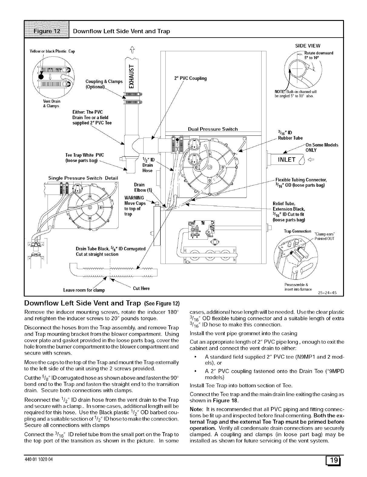
Downflow Left Side Vent and Trap (SeeFigure 12)
Remove the inducer mounting screws, rotate the inducer 180 °
and retighten the inducer screws to 20" pounds torque.
Disconnect the hoses from the Trap assembly, and remove Trap
and Trap mounting bracket from the blower compartment. Using
cover plate and gasket provided in the loose parts bag, cover the
hole from the burner compartment to the blower compartment and
secure with screws.
Move the caps to the top of the Trap and mount the Trap externally
to the left side of the unit using the 2 screws provided.
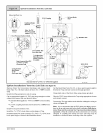
Cut the 5/8" ID corrugated hose as shown above and fasten the 90 °
bend end to the Trap and fasten the straight end to the transition
drain. Secure both connections with clamps.
Reconnect the 1/2" ID drain hose from the vent drain to the Trap
and secure with a clamp.. In some cases, additional length will be
required for this hose. Use the Black plastic 1/2" OD barbed cou-
pling and a suitable section of 1/2" ID hose to make the connection.
Secure all connections with clamps
Connect the 3/16" ID relief tube from the small port on the Trap to
the top port of the transition as shown in the picture. In some
cases, additional hose length will be needed. Use the clear plastic
3/16" OD flexible tubing connector and a suitable length of extra
3/16" ID hose to make this connection.
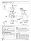
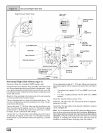
Install the vent pipe grommet into the casing
Cut an appropriate length of 2" PVC pipe long, enough to exit the
cabinet and connect the vent drain to either:
• A standard field supplied 2" PVC tee (N9MP1 and 2 mod-
els), or
• A 2" PVC coupling fastened onto the Drain Tee (*9MPD
models)
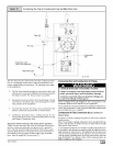
Install Tee Trap into bottom section of Tee.
Connect the Tee trap and the main drain line exiting the casing as
shown in Figure 18.
Note: It is recommended that all PVC piping and fitting connec-
tions be fit up and inspected before final cementing. Both the ex-
ternal Trap and the external Tee Trap must be primed before
operation. Verify all condensate drain connections are securely
clamped. A coupling and clamps (in loose part bag) may be
installed as shown for future servicing of the vent system.
44001 102004 E_