


UpflowInstallationsVentthru LeftSide
Yellow or black Plastic Cap
2" PVCCoupling
ONLY
Coupling
VentDrain Either: The PVC
& Clamps Drain Tee or a field
supplied 2" PVC Te_
Dual Pressure Switch Detail
DrainConnector Black PVC
314"PVCX 112"CPVC
(Loosepartsbag)
TeeTrapWhite PVC
(loosepartsbag)
Black (Movefrom
bottom ofdraintee
ifinstalled)
Casing Grommet
Black Rubber
s/8" ID
(Loose parts bag)
oj
Single Pressure Switch
Sl8"IDHose
& Clamps
ID RubberTube
SIDE VIEW
,,,_ Rotate downward
NOTET Bw]t-in channel will
be angled 5° to 10° also.
Drain LineVentTee3/4"PVCor1/2"CPVC(Fieldsupplied)
25-24-43
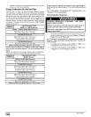
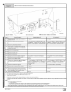
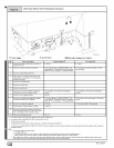
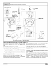
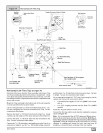
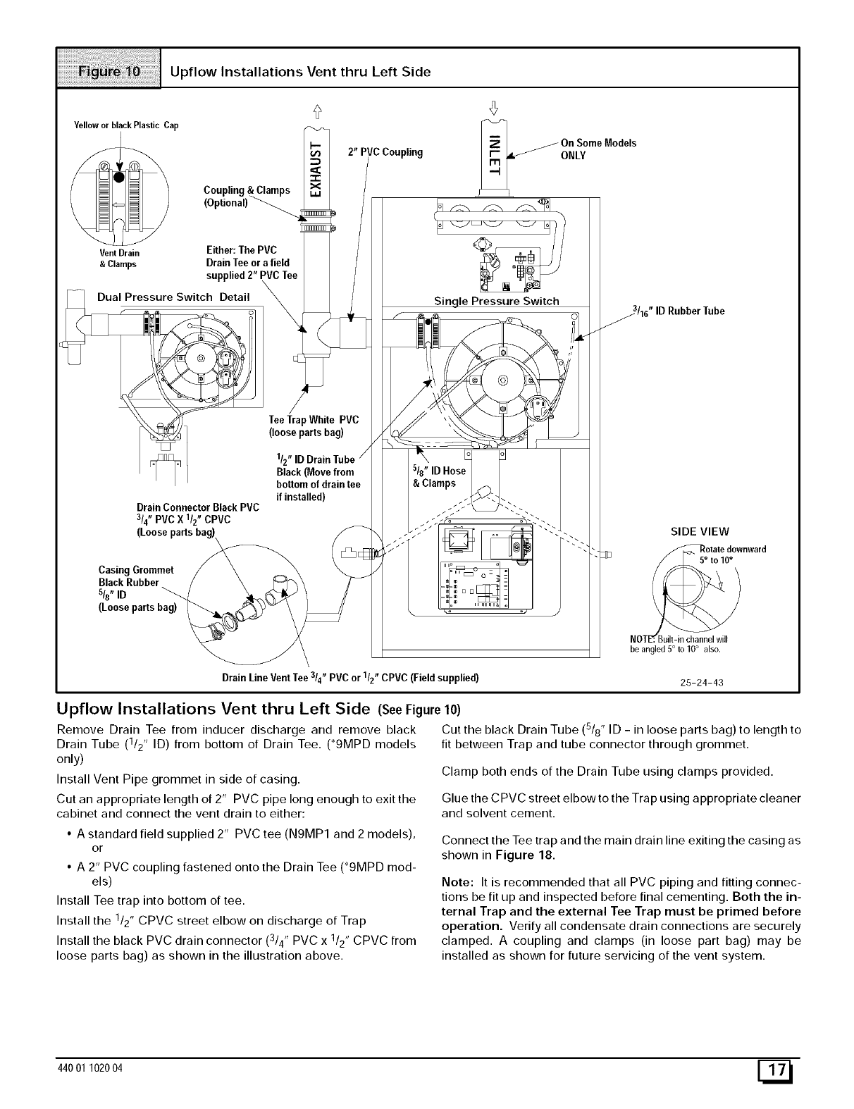
Upflow Installations Vent thru Left Side (See Figure 10)
Remove Drain Tee from inducer discharge and remove black
Drain Tube (1/2" ID) from bottom of Drain Tee. (*9MPD models
only)
Install Vent Pipe grommet in side of casing.
Cut an appropriate length of 2" PVC pipe long enough to exit the
cabinet and connect the vent drain to either:
• A standard field supplied 2" PVC tee (N9MP1 and 2 models),
or
• A 2" PVC coupling fastened onto the Drain Tee (*9MPD mod-
els)
Install Tee trap into bottom of tee.
Install the 1/2" CPVC street elbow on discharge of Trap
Install the black PVC drain connector (3/4" PVC x 1/2" CPVC from
loose parts bag) as shown in the illustration above.
Cut the black Drain Tube (5/8" ID - in loose parts bag) to length to
fit between Trap and tube connector through grommet.
Clamp both ends of the Drain Tube using clamps provided.
Glue the CPVC street elbow to the Trap using appropriate cleaner
and solvent cement.
Connect the Tee trap and the main drain line exiting the casing as
shown in Figure 18.
Note: It is recommended that all PVC piping and fitting connec-
tions be fit up and inspected before final cementing. Both the in-
ternal Trap and the external Tee Trap must be primed before
operation. Verify all condensate drain connections are securely
clamped. A coupling and clamps (in loose part bag) may be
installed as shown for future servicing of the vent system.
440O1102004 E_