


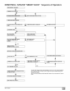
Concentric Termination Kit
NAHA001CV & NAHA002CV Venting
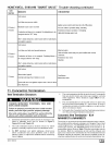
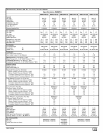
........................................................Table for N9MP2 Models
50,000 & 80,000 Btuh Furnaces
NAHA002CV - 35' & (4) 90° elbows with 2" PVC pipe or
NAHA001CV - 65' & (4) 90° elbows with 3" PVC pipe
75,000 Btuh Furnaces
NAHA002CV - 20' & (2) 90° elbows with 2" PVC pipe or
NAHA002CV - 35' & (4) 90° elbows with 2" PVC pipe &
Long Vent Kit (See Tech. Manual) or
NAHA001CV - 65' & (4) 90° elbows with 3" PVC pipe
100,000 Btuh Furnace
NAHA001CV - 35' & (4) 90° elbows with 3" PVC pipe or
NAHA001CV - 65' & (4) 90° elbows with 3" PVC pipe &
Long Vent Kit (See Tech. Manual)
125,000 Btuh Furnace
NAHA001CV - 35' & (4) 90 ° elbows with 3" PVC pipe
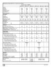
1. Do not include the field supplied 45 °elbow in the total elbow
count,
2, If more than four elbows are required, reduce the length of
both the inlet and the exhaust pipes five feet for each
additional elbow used,
3, Elbows are DWV long radius type for 2" and 3" vents,
NOTE: Feet of pipe is whichever pipe run is the longest, either
inlet or outlet side.
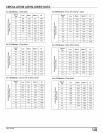
If assembly needs to be extended to meet height or side wall thick-
ness requirement, the two pipes supplied in the kit may be re-
placed by using the same diameter solid, single (no coupling
connections) field supplied SDR-26 PVC (ASTM D2241) pipes.
Do not extend dimension D more than 60". (See Figure 47)
Do not use field supplied couplings to extend the pipes.
Airflow restriction will occur and the furnace pressure switch
may cause intermittent operation.
5,
Partially assemble the concentric vent termination kit.
Clean and cement the parts using the procedures for Join-
ing Pipe and Fittings section of the manual. A) Cement the Y
Concentric fitting to the 4" diameter kit pipe. (See
Figure 48) B) Cement the 3" rain cap to the 21/2" diameter
kit part. (See Figure 48) NOTE: A field supplied stainless
steel screw may be used to secure the rain cap to the pipe
instead of cementing when field disassembly is desired for
cleaning (See Figure 48)
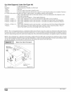
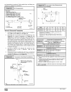
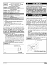
Rain Cap to Vent Pipe Assembly
25-22-02
Drill clearance hole in rain
cap and pilot hole in vent pipe.
_el screw
(Field supplied)
CARBON MONOXIDE POISONING HAZARD
Failure to follow this warning could result in death,
personal injury and/or property damage.
When using the alternate screw assembly method,
drill a clearance hole in the rain cap and a pilot hole
in the vent pipe for the screw size being used.
Failure to drill adequate holes may cause cracking
of the PVC components, allowing flue gases to be
recirculated.
CARBON MONOXIDE POISONING HAZARD
Failure to follow this warning could result in death,
personal injury and/or property damage.
Do not operate the furnace with the rain cap
removed as recirulation of the flue gases may
occur. Water may also collect inside the larger
combustion air pipe and flow to the burner
enclosure.
6. Install the Y concentric fitting and the pipe assemblythrough
the structure's hole. For vertical termination, install the parts
through the field supplied roof boot/flashing. NOTE: Do not
allow insulation or other materials to accumulate inside the
pipe assembly when installing through the structure's hole.
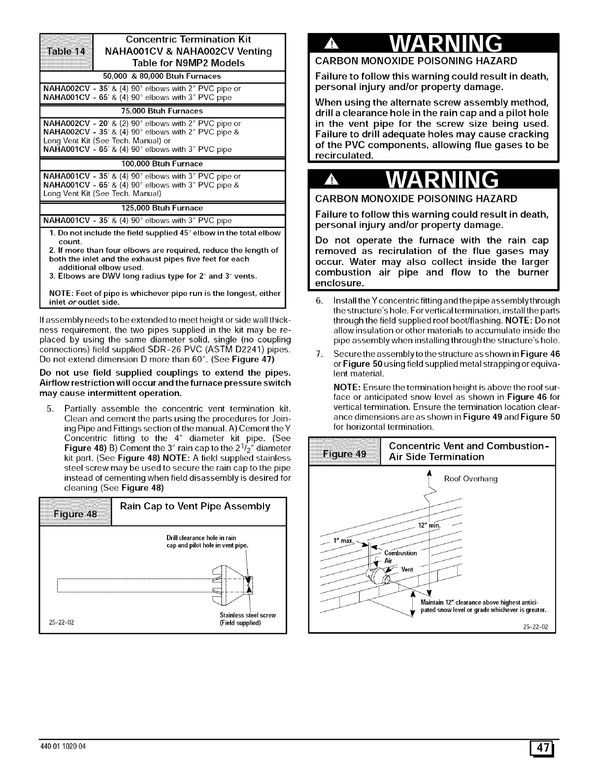
7. Securethe assemblyto the structure as shown in Figure 46
or Figure 50 using field supplied metal strapping or equiva-
lent material.
NOTE: Ensure the termination height is above the roof sur-
face or anticipated snow level as shown in Figure 46 for
vertical termination. Ensure the termination location clear-
ance dimensions are as shown in Figure 49 and Figure 50
for horizontal termination.
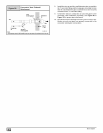
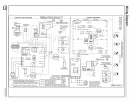
Concentric Vent and Combustion-
Air Side Termination
Roof Overhang
Maintain12" clearanceabove highestantici-
patedsnow levelor gradewhichever is greater.
25-22-02
44001 102004 [_