


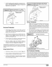
7. Ductwork and Filter
CARBON MONOXIDE POISONING HAZARD.
Failure to properly seal duct could result in death
and/or personal injury.
Do NOT draw return air from inside a closet or utility
room where furnace is located. Return air duct
MUST be sealed to furnace casing.
Installation
NOTE: Design and install air distribution system to comply with Air
Conditioning Contractors of Arnerica manuals andlor NFPA pam-
phlets 90A and 90B or other approved methods that conform to lo-
cal codes and good trade practices.
I. When furnace supply ducts carry air outside furnace area,
seal return air duct to furnace casing and terminate duct out-
side furnace space.
2. Install air conditioning cooling coil (evaporator) on outlet
side of furnace.
3. For furnaces installed without a cooling coil it is recom-
mended that the outlet duct be provided with a removable
access panel. This panel should be accessible when the
furnace is installed so the exterior of the heat exchanger can
be viewed for inspections. The access panel MUST be
sealed to prevent leaks.
4. If separate evaporator and blower units are used, install
good sealing dampers for air flow control. Chilled air going
through the furnace could cause condensation and shorten
the furnace life.
NOTE: Dampers (field supplied) can be either automatic or manu-
al. Manually operated dampers MUST be equipped with a means
to prevent furnace or air conditioning operation unless da roper is in
the full heat or cool position.
CARBON MONOXIDE POISONING HAZARD.
Failure to follow this warning could result in death,
personal injury and/or property damage.
Cool air passing over heat exchanger can cause
condensate to form resulting in heat exchanger
failure.
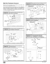
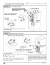
Connections
NOTE: On upflow installations, return air can enter through either
side, both sides, or the bottom. On horizontal or downflow installa-
tions the return air must enter through the knockout opening in the
lower panel of the furnace. Return air can not enter through rear of
the furnace. When the furnace is located in an area near or adja-
cent to the living area, the system should be carefully designed
with returns to minimize noise transmission through the return
grille. Any blower moving a high volume of air will produce audible
noise which could be obJectionable to when the unit is located very
close to living areas. It is advisable to route the return air ducts un-
der the floor or through the attic.
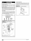
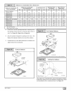
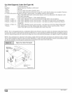
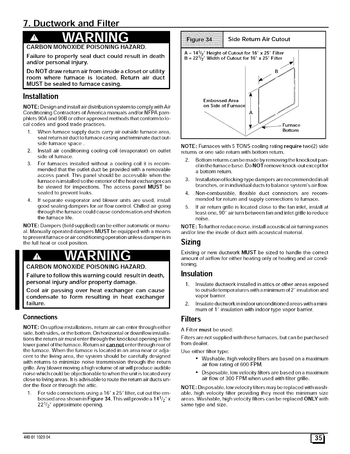
I. For side connections using a 16" x 25" filter, cut out the em-
bossed area shown in Figure 34. This will provide a 14112,, x
22112,,approximate opening.
Side Return Air Cutout
= Height of Cutout for 16" x 25" Filter
AB 22112"141/2"Width of Cutout for 16" x 25" Filter _ rll
Embossed Area
on Side of Furnace j_-
_'_ Furnace
" Bottom
NOTE: Furnaces with 5 TONS cooling rating require two(2) side
returns or one side return with bottom return.
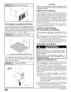
2. Bottom returns can be made by removing the knockout pan-
el in the furnace base. Do NOT remove knock-out except for
a bottom return.
3. Installation of locking-type dampers are recommended in all
branches, or in individual ducts to balance system's air flow.
4. Non-combustible, flexible duct connectors are recom-
mended for return and supply connections to furnace.
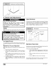
5. If air return grille is located close to the fan inlet, install at
least one, 90 ° air turn between fan and inlet grille to reduce
noise.
NOTE: To further reduce noise, install acoustical air turning vanes
and/or line the inside of duct with acoustical material.
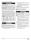
Sizing
Existing or new ductwork MUST be sized to handle the correct
amount of airflow for either heating only or heating and air condi-
tioning.
Insulation
1. Insulate ductwork installed in attics or other areas exposed
to outside temperatures with a minimum of 2" insulation and
vapor barrier.
2. Insulate ductwork in indoor unconditioned areas with amini-
mum of 1" insulation with indoor type vapor barrier.
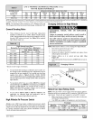
Filters
A Filter must be used:
Filters are not supplied with these furnaces, but can be purchased
from dealer.
Use either filter type:
• Washable, high velocity filters are based on a maximum
air flow rating of 600 FPM.
• Disposable, Iowvelocity filters are based on a maximum
air flow of 300 FPM when used with filter grille.
NOTE: Disposable, low velocity filters may be replaced with wash-
able, high velocity filter providing they meet the minimum size
areas. Washable, high velocity filters can be replaced ONLY with
same type and size.
44001 102004 E_