


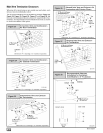
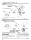
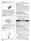
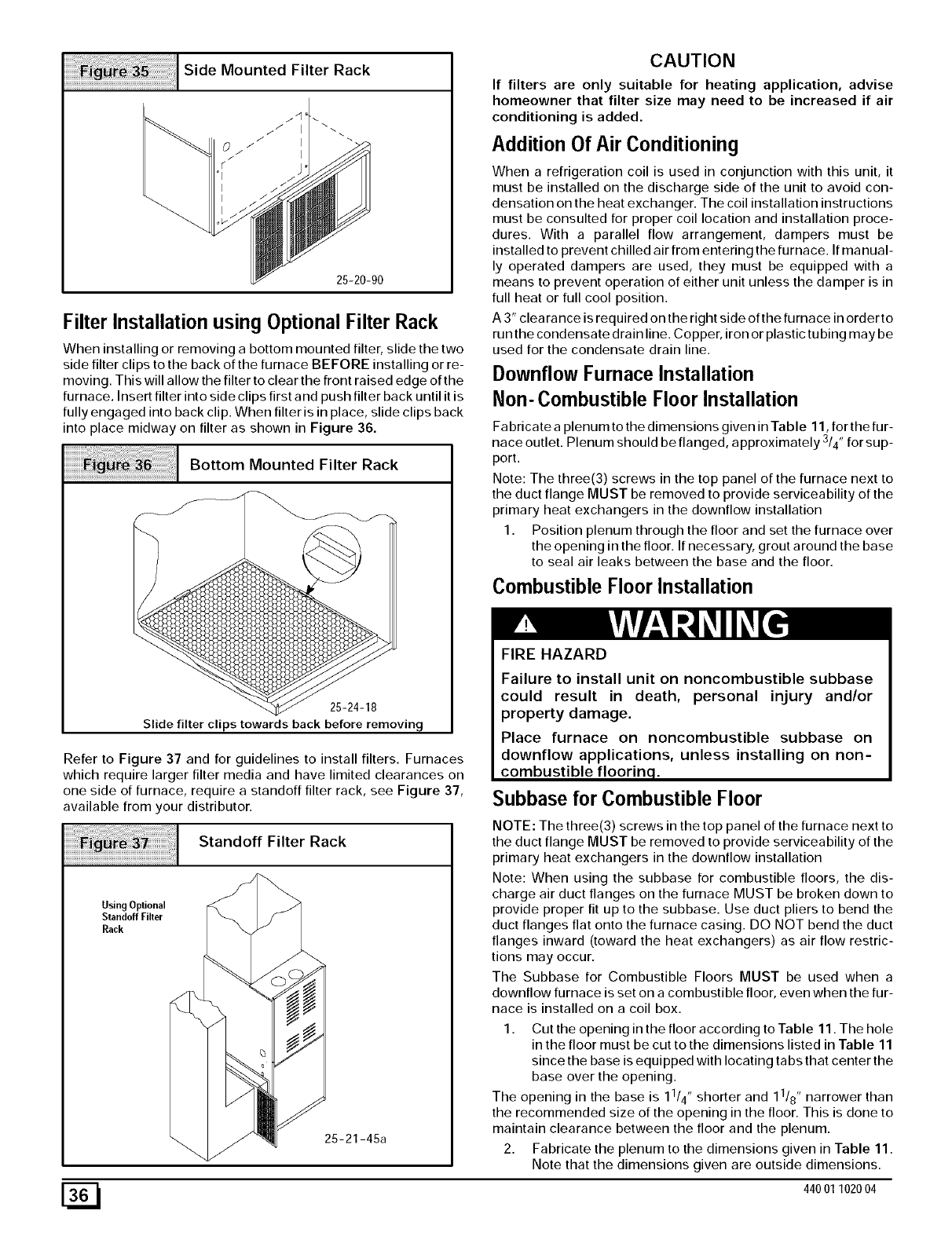
Mounted Filter Rack
25-20-90
Filter Installation using Optional Filter Rack
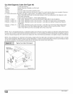
When installing or removing a bottom mounted filter, slide the two
side filter clips to the back of the furnace BEFORE installing or re-
moving. This will allow the filter to clear the front raised edge of the
furnace. Insert filter into side clips first and push filter back until it is
fully engaged into back clip. When filter is in place, slide clips back
into place midway on filter as shown in Figure 36.
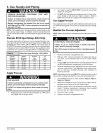
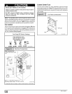
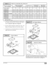
Bottom Mounted Filter Rack
25-24-18
Slide filter clips towards back before removing
Refer to Figure 37 and for guidelines to install filters. Furnaces
which require larger filter media and have limited clearances on
one side of furnace, require a standoff filter rack, see Figure 37,
available from your distributor.
Standoff Filter Rack
UsingOptional
Standoff Filter
Rack
25-21-45a
CAUTION
If filters are only suitable for heating application, advise
homeowner that filter size may need to be increased if air
conditioning is added.
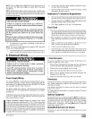
Addition Of Air Conditioning
When a refrigeration coil is used in conjunction with this unit, it
must be installed on the discharge side of the unit to avoid con-
densation on the heat exchanger. The coil installation instructions
must be consulted for proper coil location and installation proce-
dures. With a parallel flow arrangement, dampers must be
installed to prevent chilled air from entering the furnace. If ma nual-
ly operated dampers are used, they must be equipped with a
means to prevent operation of either unit unless the damper is in
full heat or full cool position.
A 3" clearance is required on the right side ofthe furnace in order to
run the condensate drain line. Copper, iron or plastic tubing may be
used for the condensate drain line.
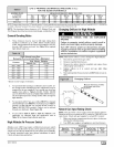
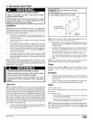
Downflow Furnace Installation
Non- Combustible Floor Installation
Fabricate a plenum to the dimensions given in Table 11, for the fur-
nace outlet. Plenum should be flanged, approximately 3/4" for sup-
port.
Note: The three(3) screws in the top panel of the furnace next to
the duct flange MUST be removed to provide serviceability of the
primary heat exchangers in the downflow installation
1. Position plenum through the floor and set the furnace over
the opening in the floor. If necessary, grout around the base
to seal air leaks between the base and the floor.
Combustible Floor Installation
FIRE HAZARD
Failure to install unit on noncombustible subbase
could result in death, personal injury and/or
property damage.
Place furnace on noncombustible subbase on
downflow applications, unless installing on non-
combustible floorinq.
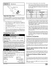
;ubbase for Combustible Floor
NOTE: The three(3) screws in the top panel of the furnace next to
the duct flange MUST be removed to provide serviceability of the
primary heat exchangers in the downflow installation
Note: When using the subbase for combustible floors, the dis-
charge air duct flanges on the furnace MUST be broken down to
provide proper fit up to the subbase. Use duct pliers to bend the
duct flanges flat onto the furnace casing. DO NOT bend the duct
flanges inward (toward the heat exchangers) as air flow restric-
tions may occur.
The Subbase for Combustible Floors MUST be used when a
downflow furnace is set on a combustible floor, even when the fur-
nace is installed on a coil box.
1. Cut the opening in the floor according to Table 11. The hole
in the floor must be cut to the dimensions listed in Table 11
since the base is equipped with locating tabs that center the
base over the opening.
The opening in the base is 11/4', shorter and 11/8', narrower than
the recommended size of the opening in the floor. This is done to
maintain clearance between the floor and the plenum.
2. Fabricate the plenum to the dimensions given in Table 11.
Note that the dimensions given are outside dimensions.
[_ 44001102004