


iiiiiiiiiiiiiiiiiiiiiiiiiiii!¸I¸!!!ii¸!iii¸I¸I¸I¸I¸!!i!i!!!i¸jijiiiii!!iil i!ii!i
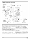
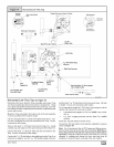
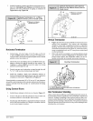
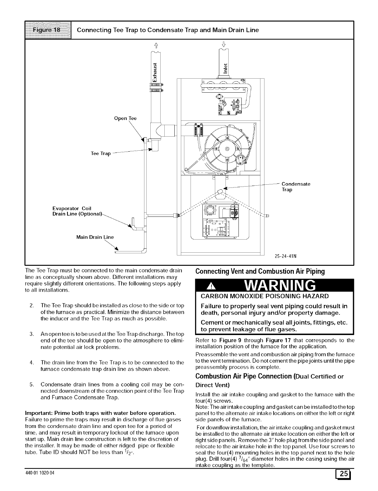
Connecting Tee Trap to Condensate Trap and Main Drain Line
Open Tee
\
Tee Trap/_---_
Evaporator Coil
Drain Line (Optional)-.................._]_E
Main Drain Line
&
E B
,m o
o_ /
Condensate
Trap
25-24-41N
The Tee Trap must be connected to the main condensate drain
line as conceptually shown above. Different installations may
require slightly different orientations. The following steps apply
to all installations.
2. The Tee Trap should be installed as close to the side or top
of the furnace as practical. Minimize the distance between
the inducer and the Tee Trap as much as possible.
3. An open tee is to be used at the Tee Trap discharge. The top
end of the tee should be open to the atmosphere to elimi-
nate potential air lock problems.
4. The drain line from the Tee Trap is to be connected to the
furnace condensate trap drain line as shown above.
5. Condensate drain lines from a cooling coil may be con-
nected downstream of the connection point of the Tee Trap
and Furnace Condensate Trap.
Important: Prime both traps with water before operation.
Failure to prime the traps may result in discharge of flue gases
from the condensate drain line and open tee for a period of
time, and may result in temporary lockout of the furnace upon
start up. Main drain line construction is left to the discretion of
the installer. It may be made of either ridged pipe or flexible
tube. Tube ID should NOT be less than 1/2,,.
44001 102004
Connecting Vent and Combustion Air Piping
CARBON MONOXIDE POISONING HAZARD
Failure to properly seal vent piping could result in
death, personal injury and/or property damage.
Cement or mechanically seal alljoints, fittings, etc.
to prevent leakage of flue gases.
Refer to Figure 9 through Figure 17 that corresponds to the
installation position of the furnace for the application.
Preassemble the vent and combustion air piping from the furnace
to the vent termination. Do not cement the pipe joints until the pipe
preassembly process is complete.
Combustion Air Pipe Connection (Dual Certified or
Direct Vent)
Install the air intake coupling and gasket to the furnace with the
four(4) screws.
Note: The air intake cou piing and gasket ca n be installed to the top
panel to the alternate air intake locations on either the left or right
side panels of the furnace.
For downflow installation, the air intake coupling and gasket must
be installed to the alternate air intake location on either the left or
right side panels. Remove the 3" hole plug from the side panel and
relocate to the air intake hole in the top panel. Use four screws to
seal the four(4) mounting holes in the top panel next to the hole
plug. Drill four(4) 7/64" diameter holes in the casing using the air
intake coupling as the template.
[!N