


Convector 460/560PTR - 25 - ©Rinnai
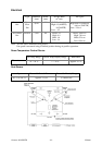
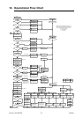
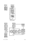
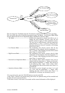
10. Operational Flow Chart
H
eater
ON
Power Point ON
I
II
ON/OFF SW.
Normal
No
Yes
No
No
Yes
O
N
/O
FF
s
w.
O
N
Yes
Operation/Comb. Ind.
Illuminates (Green)
Display time
6
Room temp.
A
R
.
F
d
e
t
ec
ti
on
sw.temp. fuse
Normal
III
T/C output
<10mV
No
No
No
Yes
Yes
Conv. motor Hi ON
Conv. motor Lo ON
Yes
S
p
arker ON
Solenoid SV1 ON
Solenoid SV2 ON
POV Med ON
(
After 0.2 sec
)
Overheat TH
Normal
R
oom
T
emp.
Thermistor
Normal
POV Hi ON
Yes
No
No
Yes
T/C output
(Ú1mV)
Operation/Comb. Indic.
Illuminates (Red)
Conv. motor med ON
S
p
arker OFF
Conv. motor Hi ON
R
ev.
fl
ame
d
etect
i
on
sw. OFF
(
150
E
C
)
No
Yes
2
Tem
p
. check starts
C.M. Mod. control
M.V modulatin
g
. control
OH Thermistor
activates (65
E
C)
Filter indicator flashes
Safety device
activated
No
No
Yes
(
after a
pp
rox. 3 sec.
)
(
30 sec. after
(
b
))
(
10 sec. after
(
c
))
Ú1 Igniton sensed
output is the initial T/C
check output +2mV
(min.3mV. max. 18mV)
Fan motor error
<350rpm, 4 sec)
B
C.M med ON
S
p
arker OFF
S
p
arker OFF
S
p
arker OFF
(
a
)
(
c
)
73
Operation/Comb.
Ind. flashes
(
red
)
71
Operation/Comb.
Ind. flashes
(
red
)
70
Operation/Comb.
Ind. flashes
(
red
)
14
Operation/Comb.
Ind. flashes
(
red
)
Filter Ind. flashes
03
Operation/Comb.
Ind. flashes
(
red
)
72
Operation/Comb.
Ind. flashes
(
red
)
(
After a max. of 50 sec
)
33
Operation/Comb.
Ind. flashes
(
red
)
34
31
Operation/Comb.
Ind. flashes
(
red
)
32
Operation/Comb.
Ind. flashes
(
red
)
11
62
Operation/Comb.
Ind. flashes
(
red
)
12
Cause
e
limin
ated
Power Point OFF
All indicators OFF
ON/OFF Switch OFF
C.M. OFF
C.M. OFF
(
After max.255 sec
)
(
Disconnection
)
(
Short circuit
)
C.M. med ON
SV1
,
SV2 OFF
POV OFF
(
Disconnection
)
(
Short circuit
)
Co
nv. m
oto
r
O
FF
C.M. med OFF
SV1
,
SV2 OFF
POV OFF
(
After 5 sec
)
SV1, SV2 OFF
POV OFF
Co
nv. m
oto
r
O
FF
(
150~255 sec
)
14
Operation/Comb.
Ind. flashes
(
red
)
Filter Ind. flashes
Thermal fuse
discon.
(
216
E
C
)
OH thermistor
activated
(
70
E
C
)
Gas disconn. device
when tilting is
activated (50~80
E
C)
03
Operation/Comb.
Ind. flashes
(
red
)
Incomplete comb.
prevention safety
device is activated
(*mV, 5 sec)
12
Operation/Comb.
Ind. flashes
(
red
)
OFF Function act.
>40
E
C 10 min
16
Operation/Comb.
Ind. flashes
(
red
)
ON/OFF switch
Error (for 15 sec)
70
Operation/Comb.
Ind. flashes
(
red
)
R
e-
i
ns
t
a
t
emen
t
of power
00
Operation/Comb.
Ind. flashes
(
red
)
Power failure
Operation ceases
C.M Med ON
SV1
,
SV2 OFF
M.V POV OFF
C.M. med ON
LPGNG
I: Micro-computer and E2PROM's signal path normal
II: Solenoid valve and Modulation valve rotation normal
III: Gas disconnection device normal when tilting
C.M.: Convection Motor
R.F.: Reverse Flame
SV: Solenoid
1
2
3
4
5
Fan motor
>6 r.p.m
6
62
Operation/Comb.
Ind. flashes
(
red
)
10
11
9
5
5
PROP.G
5
9
2
10
3
12
11
1
Yes
(
10 sec after
(
a
))
C
.M.
O
FF
No
Yes
5
7
8
8
9
(
b
)
16mV14mV 16mV
*