


50
6
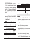
. Perform leakage test on gas valves. (See Fig. 48.)
7. Test air switch in accordance with manufacturer’s
instructions. (Turn panel switch to the “On” posi-
t
ion until blower is proven, then turn the switch to
“Off.”
8. Inspect and clean burner using shop air.
As Required
1. Recondition or replace low water cut-off device (if
equipped).
2. Check drip leg and gas strainers.
3. Check flame failure detection system. (See “Post
Start-Up Check,” page 45.)
4. Check igniter. (Resistance reading should be 42-
70 ohms at ambient temperature).
5. Check flame signal strength. (Flame signal should
be greater than 1 microampere as measured at
the 2 pins on the upper left corner of the ignition
control).
6. Check firing rate control by checking the manifold
pressure. (See “Manifold Check” on page 43.)
7. Test safety/safety relief valves in accordance with
ASME Heater and Pressure Vessel Code Section
IV.
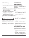
Filter Maintenance
• Inspect quarterly
• Replace when tracking pressure exceeds -0.5 in.
WC at 100% fan speed, except for models 1003,
1753 and 2003, which need to be replaced when
tracking pressure exceeds -0.7 in. WC at 100% fan
speed.
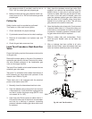
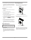
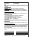
Filter Replacement
1. Remove the filter box cover by loosening and
removing the two wing nuts holding it in place.
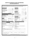
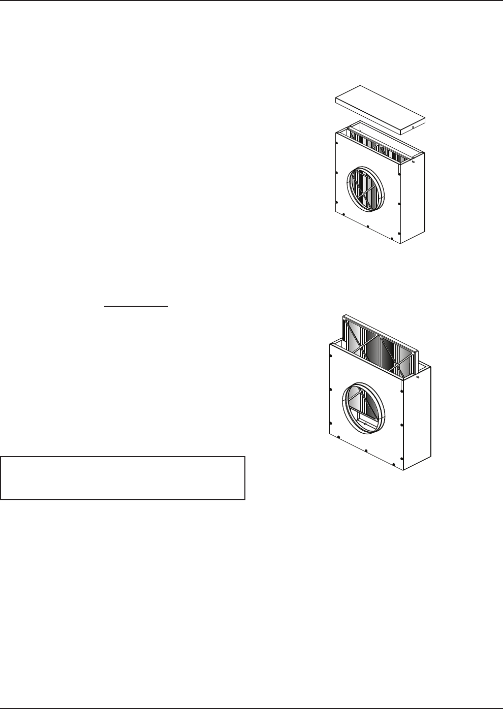
2. Remove the filter by lifting it straight up and out of
the slot in the filter box.
3. Reverse steps 1 and 2 to install the new filter. Use
Raypak replacement filters, kit number 012552F
(12”X12”) for models 503-1103 and kit number
012553F (16”X16”) for models 1253-2003.
NOTE: Use Raypak replacement filters, kit number
012552F (12”X12”) for models 503-1003 and kit
number 012553F (16”X16”) for models 1253-2003.
Fig. 49: Remove the Air Filter Box Cover
Fig. 50: Remove the Air Filter