


42
Preparation
Check Power Supply
With multi-meter at incoming power, check voltage
between:
Hot - Common (≈120 VAC)
Hot - Ground (≈120 VAC)
Common - Ground (< 1 VAC)
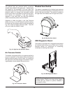
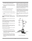
Attach Manometers to Measure Pressures
1. Turn off main gas valve.
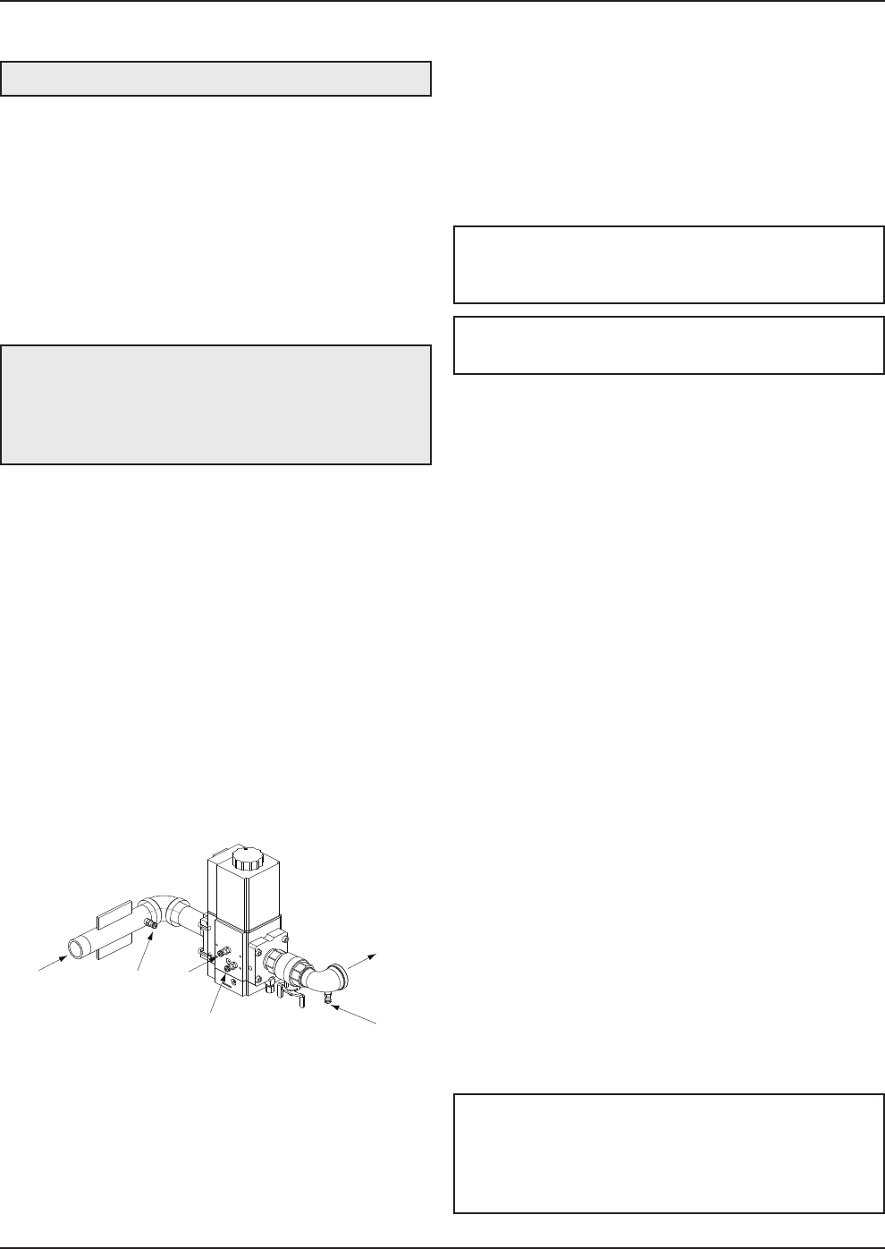
2. Attach (1) 12” scale manometer to an upstream
bleedle valve on the gas supply pipe to the heater
(Measure point “A” in Fig. 47).
3. Attach (1) 24” scale manometer to the manifold
pressure tap located on the elbow downstream of
the valve (Measure point “D” in Fig. 47).
4. Attach (1) 12” scale manometer near the fan-prov-
ing switch. Pull black cap from air pressure switch
tee and connect the manometer. NOTE: Retain
caps for reinstallation later.
Check Gas Supply Pressure
1. Slowly turn on main gas shut-off valve.
2. Read the gas supply pressure from the manome-
ter; minimum supply pressure for natural gas is 4.0
in. WC, recommended supply is 7.0 in. WC, mini-
WARNING: If Common - Ground is > 1 VAC,
STOP: Contact electrician to correct ground failure.
Failure to do this may burn out 120V-24V
transformer, or may cause other safety control
damage or failure.
Start-Up
1. Turn power on.
2. Turn on the heater, wait approximately 15 seconds
after the blower starts, the igniter should start to
glow (observable through the observation port
located at the front, bottom of the heater). Look
into the sight glass located at the bottom of the
front panel to check igniter operation. Gas valve
should open in 45-60 seconds.
3. The heater ignites at 50% of full rate (as indicated
on the LCD display of the temperature control
located in the upper right of the front panel).
4. If the burner fails to light on the first trial, it will try
for ignition up to three times before going into lock-
out with the standard ignition module. If the heater
is equipped with the optional single-try ignition
module, it will go into lockout.
5. Wait until the controller indicates 100% on the fir-
ing rate display screen (approximately 30
seconds).
Blower Check
1. Check blower suction using the manometer
attached to the fan pressure switch tee, with the
heater firing at 100% input. The reading should be
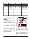
as noted in Table T for both natural and propane
gas.
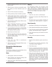
GAS
TO BURNER
A
B
C
D
Fig. 47: Gas Pressure Measurement Locations
m
um supply pressure for propane gas is 4.0 in.
WC, recommended supply is 11.0 in. WC (dynam-
ic readings, full fire input).
3
. If the gas pressure is greater than 14.0 in. WC,
turn off the main gas shut-off valve, upstream of
t
he heater.
NOTE: The values in Tables T, U and V represent
the conditions when the heater is at full firing rate at
sea level.
NOTE: Most commercially available amp probes
are not accurate enough and/or are not shielded well
enough to read accurately in the heater
environment. Blower amp draw readings are for
reference only.
WARNING: Do not turn on gas at this time.
NOTE: Pressure and combustion data are provided
with the heater.