


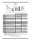
15
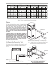
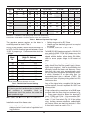
Table F: Heater Rates of Flow and Pressure Drops
20°F
T 30°F T 40°F T
Min. Flow Max. Flow
Model
No.
gpm
P (ft)
gpm
P (ft)
gpm
P (ft)
gpm
P (ft) T
gpm
P (ft) T
503 44 2.8 29 1.4 N/A N/A 25 1.1 35 100 11.3 9
753 65 6.4 44 3.1 33 1.9 33 1.9 40 100 13.8 13
1003 87 12.0 58 6.0 43 3.7 43 3.7 40 113 18.6 15
1253 109 20.9 73 10.2 54 6.2 54 6.2 40 113 22.2 19
1503 N/A N/A 87 16.0 65 9.5 65 9.5 40 113 25.5 23
1753 N/A N/A 102 22.5 76 13.4 76 13.4 40 113 27.2 27
2003 N/A N/A 116 32.0 87 18.9 87 18.9 40 116 32.0 30
Notes: Basis for minimum flow is ∆T . Basis for maximum flow is gpm.
Piping
All high points should be vented. A heater installed
above radiation level must be provided with a low wa-
ter cut-off device (sales order option F-10). This
heater, when used in connection with a refrigeration
system, must be installed so that the chilled medium is
piped in parallel with the heater with appropriate
valves to pre-vent the chilled medium from entering
the heater.
The piping system of a hot water heater connected to
heating coils located in air handling units where they
may be exposed to circulating refrigerated air, must be
equipped with flow control valves or other automatic
means to prevent gravity circulation of the heater
water during the cooling cycle. It is highly recommend-
ed that the piping be insulated.
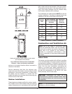
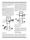
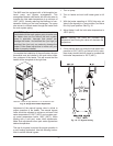
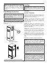
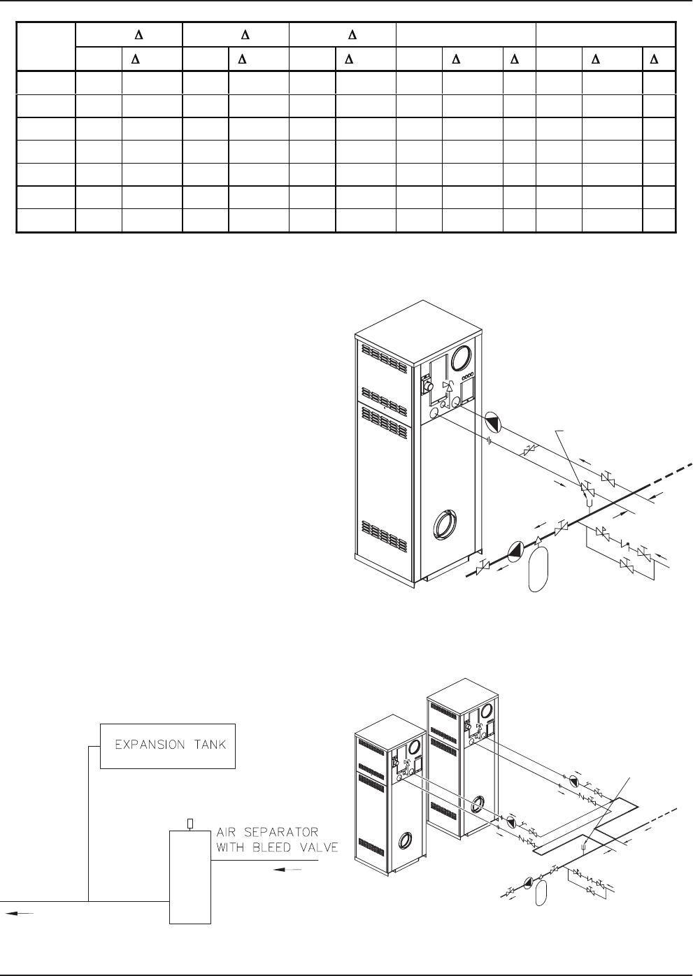
Air-Separation/Expansion Tank
All heaters should be equipped with a properly sized
expansion tank and air separator fitting as shown in
Fig. 11.
Fig. 11: Air-Separation/Expansion Tank
*
THERMOSTAT OR
SYSTEM SENSOR
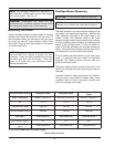
Fig. 12: Single Heater - Low-Temperature (Heat Pump)
Application with Primary/Secondary Piping
*
THERMOSTAT OR
SYSTEM SENSOR
Fig. 13: Dual Heaters (Reverse/Return)
with Primary/Secondary Piping
*Maximum 4 times the pipe diameter or 12”, whichever is less.
*Maximum 4 times the pipe diameter or 12”, whichever is less.