


27
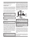
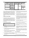
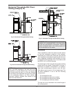
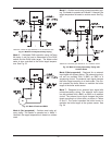
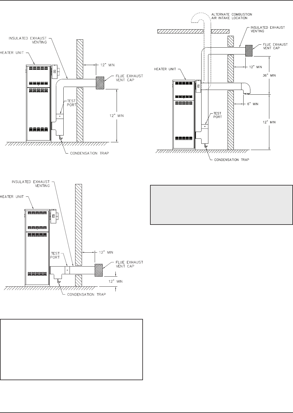
Fig. 25: Horizontal Through-the-Wall Venting
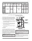
Fig. 26: Alt. Horizontal Through-the-Wall Venting
NOTE: While a drain connection is required in the
vent of all MVB installations, the drain can be ac-
complished in several different ways. The figures in
this manual show the drain in a vent tee, however,
this can also be accomplished using an inline collec-
tor for condensing stacks or an inline vertical or
horizontal collector available from several of the
listed vent manufacturers.
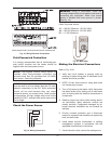
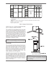
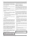
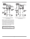
Fig. 27: Horizontal Through-the-Wall Direct Venting
CAUTION: This venting system requires the
installation of a condensate drain in the vent piping
per the vent manufacturer’s instructions. Failure to
install a condensate drain in the venting system will
void all warranties on this heater.
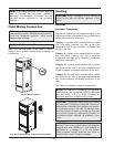
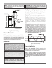
Installation
These installations utilize the heater-mounted blower
to vent the combustion products to the outdoors.
Combustion air is taken from inside the room and the
vent is installed horizontally through the wall to the out-
doors. Adequate combustion and ventilation air must
be supplied to the equipment room in accordance with
the NFGC (U.S.) or B149 (Canada).
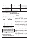
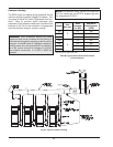
The total length of the horizontal through-the-wall flue
system should not exceed 75 equivalent ft in length. If
horizontal run exceeds 75 equivalent ft, an appropri-
ately sized variable-speed extractor must be used.
Each elbow used is equal to 10 ft of straight pipe. This
will allow installation in one of the four following
arrangements:
• 75’ of straight flue pipe
• 65’ of straight flue pipe and one elbow
• 55’ of straight flue pipe and two elbows
• 45’ of straight pipe and three elbows
The vent cap is not considered in the overall length of
the venting system.
Horizontal Through-the-Wall Direct
Venting (Category IV)