


22
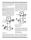
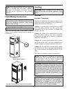
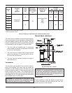
Field Wiring Connection
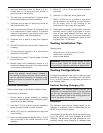
Venting
General
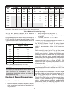
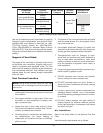
Appliance Categories
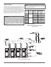
Heaters are divided into four categories based on the
pressure produced in the exhaust and the likelihood of
condensate production in the vent.
Category I – A heater which operates with a non-pos-
itive vent static pressure and with a vent gas
temperature that avoids excessive condensate pro-
duction in the vent.
Category II – A heater which operates with a non-pos-
itive vent static pressure and with a vent gas
temperature that may cause excessive condensate
production in the vent.
Category III – A heater which operates with a positive
vent pressure and with a vent gas temperature that
avoids excessive condensate production in the vent.
Category IV – A heater which operates with a positive
vent pressure and with a vent gas temperature that
may cause excessive condensate production in the
vent.
See Table K for appliance category requirements.
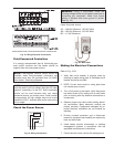
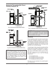
HIGH VOLTAGE
WIRING
CAUTION: Label all wires prior to disconnection
when servicing controls. Wiring errors can cause im-
proper and dangerous operation. Verify proper
operation after servicing.
Fig. 21: Wiring Location
DANGER: SHOCK HAZARD
CAUTION: Proper installation of flue venting is
critical for the safe and efficient operation of the
heater.
NOTE: For additional information on appliance
categorization, see appropriate ANSI Z21 Standard
and the NFGC (U.S.), or B149 (Canada), or
applicable provisions of local building codes.
WARNING: Contact the manufacturer of the vent
material if there is any question about the appliance
categorization and suitability of a vent material for
application on a Category III or IV vent system.
Using improper venting materials can result in
personal injury, death or property damage.
NOTE: A grounding electrode conductor shall be
used to connect the equipment grounding
conductors, the equipment enclosures, and the
grounded service conductor to the grounding
e
lectrode.
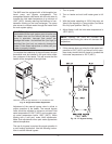
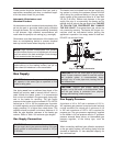
CAUTION: Condensate drains for the vent piping
are required for installations of the MVB. Follow vent
manufacturer instructions for installation and location
of condensate drains in the vent. Condensate drain
must be primed with water to prevent gas flue leak
and must be routed to an appropriate container for
neutralization before disposal, as required by local
codes.
Make sure electrical power to the heater is discon-
nected to avoid potential serious injury or damage to
components.
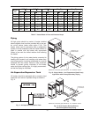
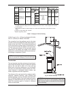
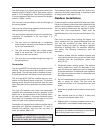
LOCATOR DIMPLES
FOR OPTIONAL
COMPONENTS
Fig. 22: Locator Dimples for Optional Components