


19
Further advice should be obtained from your pool or
spa builder, accredited pool shop, or chemical suppli-
er for the correct levels for your water.
Automatic Chlorinators and
Chemical Feeders
All chemicals must be introduced and completely dilut-
ed into the pool or spa water before being circulated
through the heater. Do not place sanitizing chemicals
in the skimmer. High chemical concentrations will
result when the pump is not running (e.g. overnight).
Chlorinators must feed downstream of the heater and
have an anti-siphoning device to prevent chemical
back-up into the heater when the pump is shut off.
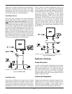
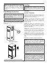
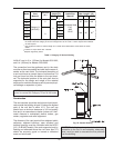
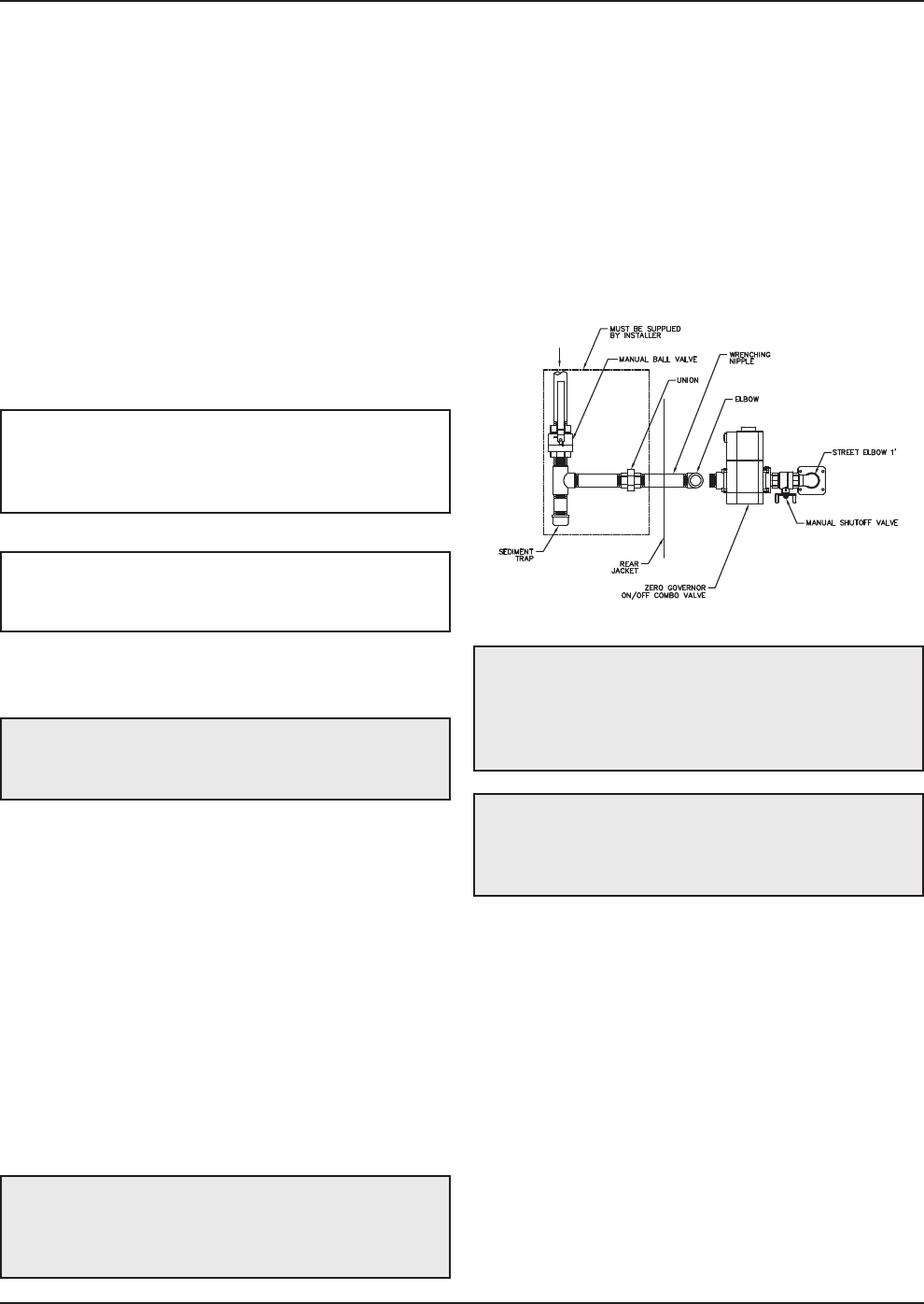
Gas Supply
Gas piping must have a sediment trap ahead of the
heater gas controls, and a manual shut-off valve lo-
cated outside the heater jacket. It is recommended
that a union be installed in the gas supply piping adja-
cent to the heater for servicing. The gas supply
pressure to the heater must not exceed 10.5 in. WC for
natural gas or 13.0 in. WC for propane gas. A pounds-
to-inches regulator must be installed to reduce the gas
supply pressure if it is higher than noted above. This
regulator should be placed a minimum distance of 10
times the pipe diameter upstream of the heater gas
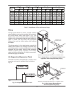
controls. Refer to Table I for maximum pipe lengths.
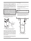
Gas Supply Connection
DANGER: Make sure the gas on which the heater
will operate is the same type as specified on the
heater’s rating plate.
CAUTION: The heater must be disconnected from
the gas supply during any pressure testing of the gas
supply system at test pressures in excess of 1/2 psi
(3.45 kPa).
T
he heater must be isolated from the gas supply pip-
ing system by closing the upstream manual shut-off
valve during any pressure testing of the gas supply
piping system at test pressures equal to or less than
1
/2 psi (3.45 kPa). Relieve test pressure in the gas
supply line prior to re-connecting the heater and its
m
anual shut-off valve to the gas supply line. FAILURE
TO FOLLOW THIS PROCEDURE MAY DAMAGE
THE GAS VALVE. Over-pressurized gas valves are
not covered by warranty. The heater and its gas con-
nections shall be leak-tested before placing the
appliance in operation. Use soapy water for leak test.
DO NOT use an open flame.
Gas Supply Pressure
A minimum of 4.0 in. WC and a maximum of 10.5 in.
WC upstream gas pressure is required under load and
no-load conditions for natural gas. A minimum of 4.0
in. WC and a maximum of 13.0 in. WC is required for
propane gas. The gas pressure regulator(s) supplied
on the heater is for low-pressure service. If upstream
pressure exceeds these values, an intermediate gas
pressure regulator, of the lockup type, must be
installed.
When connecting additional gas utilization equipment
to the gas piping system, the existing piping must be
checked to determine if it has adequate capacity for
the combined load.
Fig. 17: Gas Supply Connection
CAUTION: Do not use Teflon tape on gas line pipe
thread. A pipe compound rated for use with natural
and propane gases is recommended. Apply
sparingly only on male pipe ends, leaving the two
end threads bare.
CAUTION: Support gas supply piping with
hangers, not by the heater or its accessories. Make
sure the gas piping is protected from physical
damage and freezing, where required.
NOTE: Failure of a heat exchanger due to lime
scale build-up on the heating surface, low pH or
other chemical imbalance is non-warrantable.
NOTE: High chemical concentrates from feeders
and chlorinators that are out of adjustment will cause
rapid corrosion to the heat exchanger. Such damage
is not covered under the warranty.